
How to Use Power Supply: Examples, Pinouts, and Specs
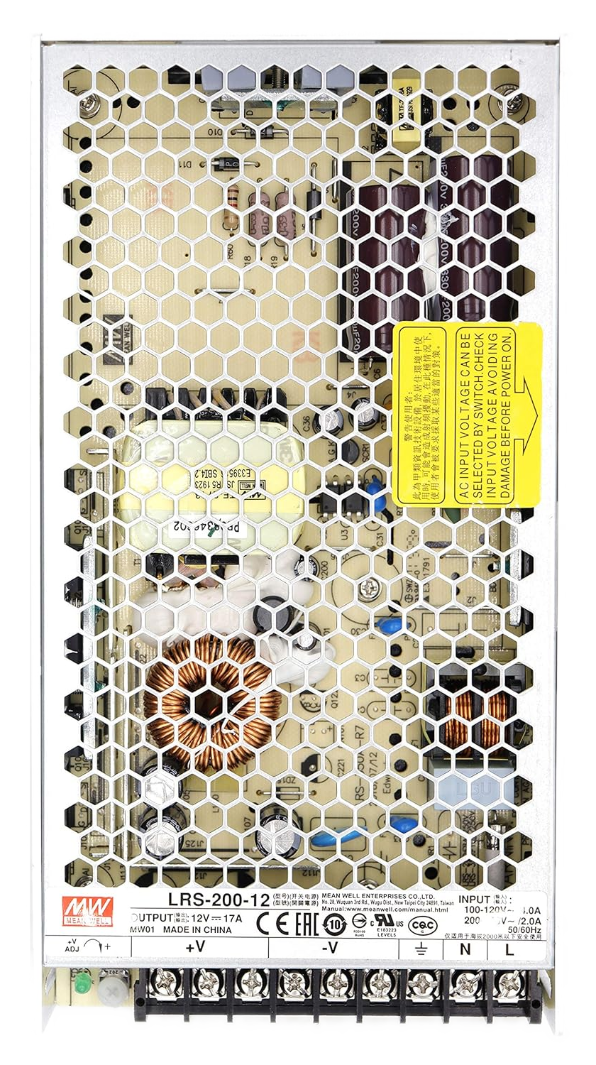
 Design with Power Supply in Cirkit Designer
Introduction
A power supply is a device that provides electrical energy to a circuit, converting AC or DC voltage from a source into a usable form for electronic components. It is an essential component in virtually all electronic systems, ensuring that devices receive the correct voltage and current for proper operation. Power supplies come in various types, including linear, switching, and programmable models, each suited for specific applications.
Explore Projects Built with Power Supply
 Open Project in Cirkit Designer
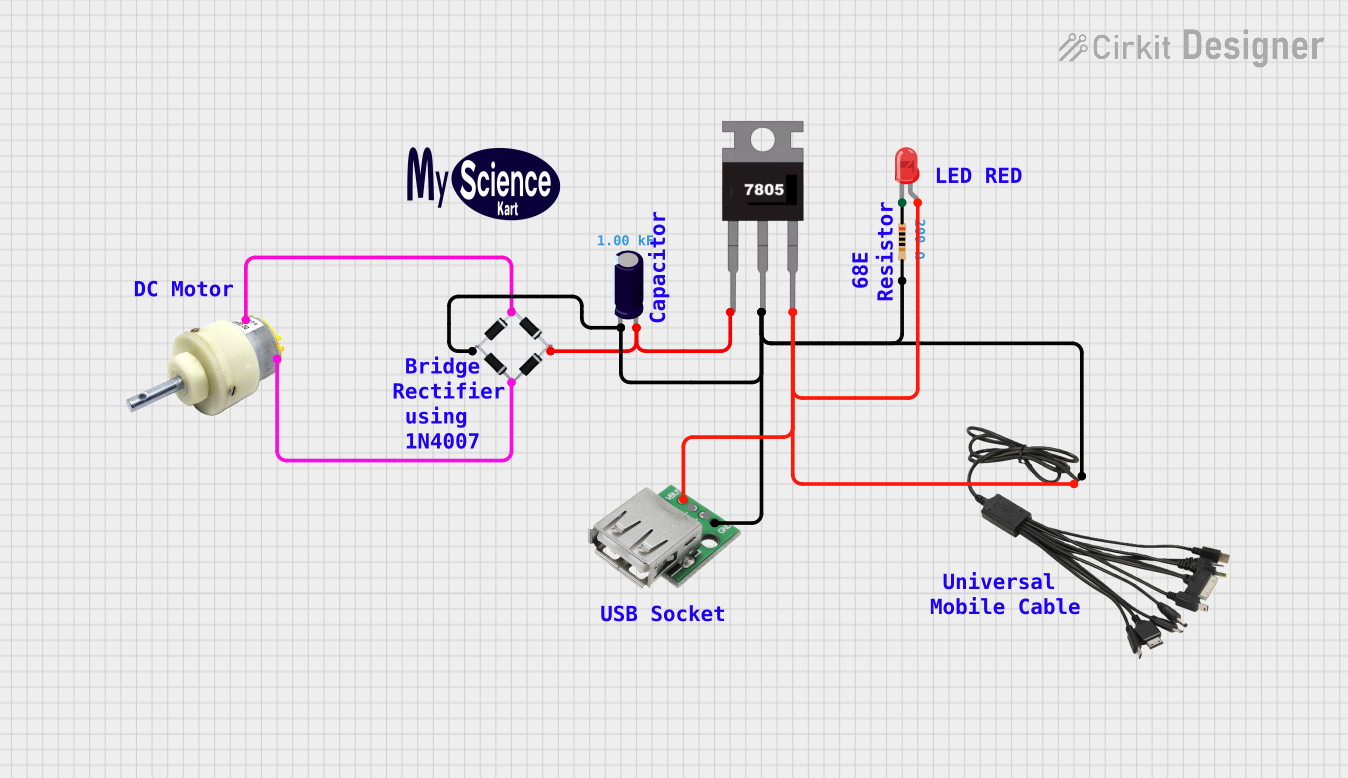 Open Project in Cirkit Designer
 Open Project in Cirkit Designer
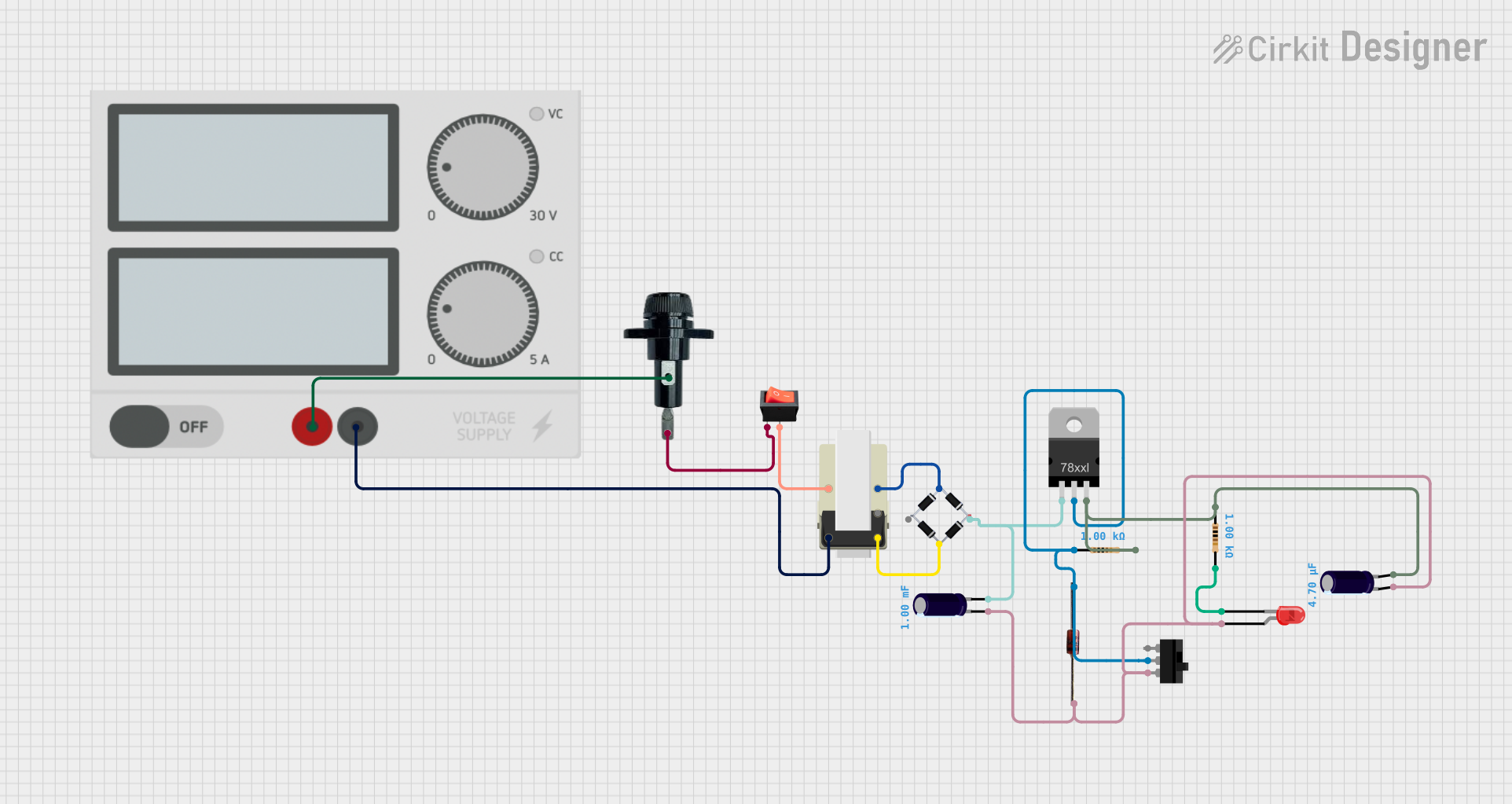 Open Project in Cirkit Designer
Explore Projects Built with Power Supply
Open Project in Cirkit DesignerOpen Project in Cirkit DesignerOpen Project in Cirkit DesignerOpen Project in Cirkit DesignerCommon Applications and Use Cases
- Powering microcontrollers, sensors, and actuators in embedded systems
- Supplying energy to industrial equipment and machinery
- Charging batteries in portable devices
- Providing stable voltage for laboratory testing and prototyping
- Powering consumer electronics such as televisions, computers, and audio systems
Technical Specifications
Below are the general technical specifications for a typical DC power supply. Specifications may vary depending on the specific model or type.
Key Technical Details
- Input Voltage: 100-240V AC, 50/60Hz (typical for universal power supplies)
- Output Voltage: Adjustable or fixed, commonly 3.3V, 5V, 12V, or 24V DC
- Output Current: Ranges from milliamps (mA) to several amps (A), depending on the model
- Power Rating: Typically 5W to 500W or more
- Efficiency: 70% to 95% (higher for switching power supplies)
- Ripple and Noise: <50mV (for high-quality supplies)
- Protection Features: Overvoltage, overcurrent, short-circuit, and thermal protection
Pin Configuration and Descriptions
The pin configuration for a power supply depends on its type. Below is an example for a DC barrel jack connector commonly used in power supplies:
| Pin | Description |
|---|---|
| Positive (+) | Supplies the positive DC voltage output. |
| Negative (-) | Provides the ground connection. |
For a more advanced power supply with screw terminals:
| Terminal | Description |
|---|---|
| V+ | Positive DC voltage output. |
| V- | Ground or negative terminal. |
| Earth (E) | Optional earth/ground connection. |
Usage Instructions
How to Use the Component in a Circuit
- Determine Voltage and Current Requirements: Identify the voltage and current requirements of your circuit or device.
- Select the Appropriate Power Supply: Choose a power supply that matches or exceeds the required voltage and current ratings.
- Connect the Power Supply:
- For DC barrel connectors, plug the connector into the device's power input.
- For screw terminals, connect the V+ terminal to the positive input of your circuit and the V- terminal to the ground.
- Power On the Supply: Turn on the power supply and verify the output voltage using a multimeter before connecting it to sensitive components.
- Monitor the Circuit: Ensure the circuit operates as expected and that the power supply does not overheat.
Important Considerations and Best Practices
- Always verify the polarity of the connections to avoid damaging your circuit.
- Use a power supply with a slightly higher current rating than required to ensure reliable operation.
- Avoid overloading the power supply beyond its rated capacity.
- For sensitive circuits, use a power supply with low ripple and noise.
- If using an adjustable power supply, double-check the output voltage before connecting it to your circuit.
Example: Using a Power Supply with an Arduino UNO
To power an Arduino UNO using a 9V DC power supply:
- Connect the positive terminal of the power supply to the Arduino's VIN pin.
- Connect the negative terminal to the GND pin.
- Ensure the power supply is set to 9V before powering on.
Here is an example Arduino sketch to blink an LED while powered by the external supply:
// Blink an LED connected to pin 13
// Ensure the Arduino is powered by a 9V DC power supply

void setup() {
  pinMode(13, OUTPUT); // Set pin 13 as an output
}

void loop() {
  digitalWrite(13, HIGH); // Turn the LED on
  delay(1000);            // Wait for 1 second
  digitalWrite(13, LOW);  // Turn the LED off
  delay(1000);            // Wait for 1 second
}
Troubleshooting and FAQs
Common Issues Users Might Face
No Output Voltage:
- Cause: The power supply is not powered on or is not connected properly.
- Solution: Check the input power source and ensure all connections are secure.
Overheating:
- Cause: The power supply is overloaded or operating in a poorly ventilated area.
- Solution: Reduce the load or improve ventilation around the power supply.
Voltage Fluctuations:
- Cause: The power supply is of low quality or the input voltage is unstable.
- Solution: Use a regulated power supply or a voltage stabilizer.
Device Not Powering On:
- Cause: Incorrect voltage or polarity.
- Solution: Verify the voltage and polarity of the power supply output.
Solutions and Tips for Troubleshooting
- Use a multimeter to measure the output voltage and ensure it matches the expected value.
- Check for loose or damaged wires and connectors.
- If the power supply has adjustable output, ensure the voltage is set correctly.
- For switching power supplies, listen for unusual noises (e.g., buzzing) that may indicate a fault.
By following these guidelines and troubleshooting tips, you can ensure reliable operation of your power supply and connected devices.