How to Use OBD-II port: Examples, Pinouts, and Specs
Introduction
The OBD-II (On-Board Diagnostics II) port is a standardized interface found in most vehicles produced after 1996. It allows for the monitoring and diagnosis of a vehicle's engine and other vital systems. Mechanics and technicians commonly use this port to retrieve error codes and performance data to troubleshoot issues. Additionally, it is used by a variety of aftermarket devices such as performance tuners, telematics systems, and insurance trackers.
Explore Projects Built with OBD-II port
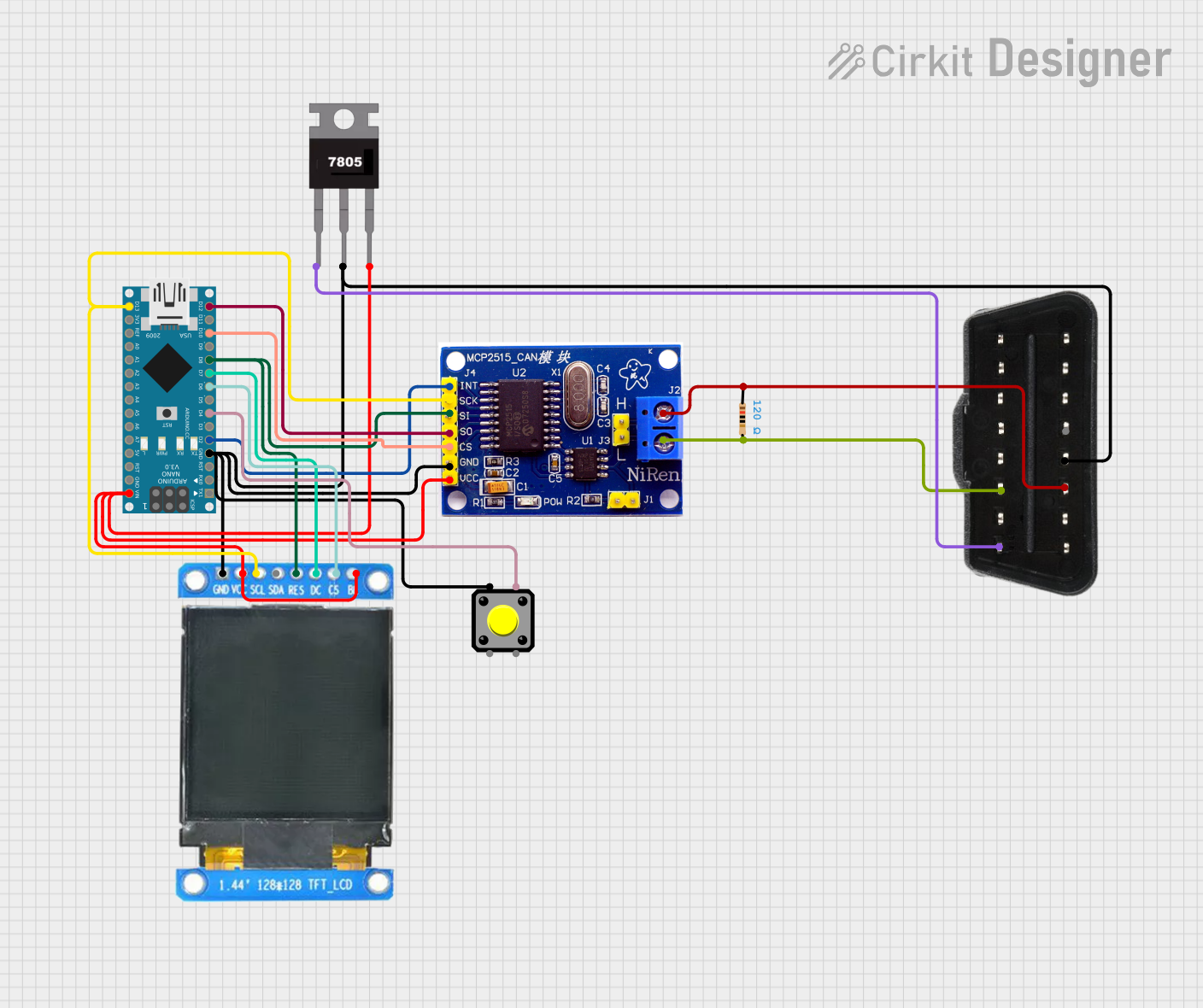
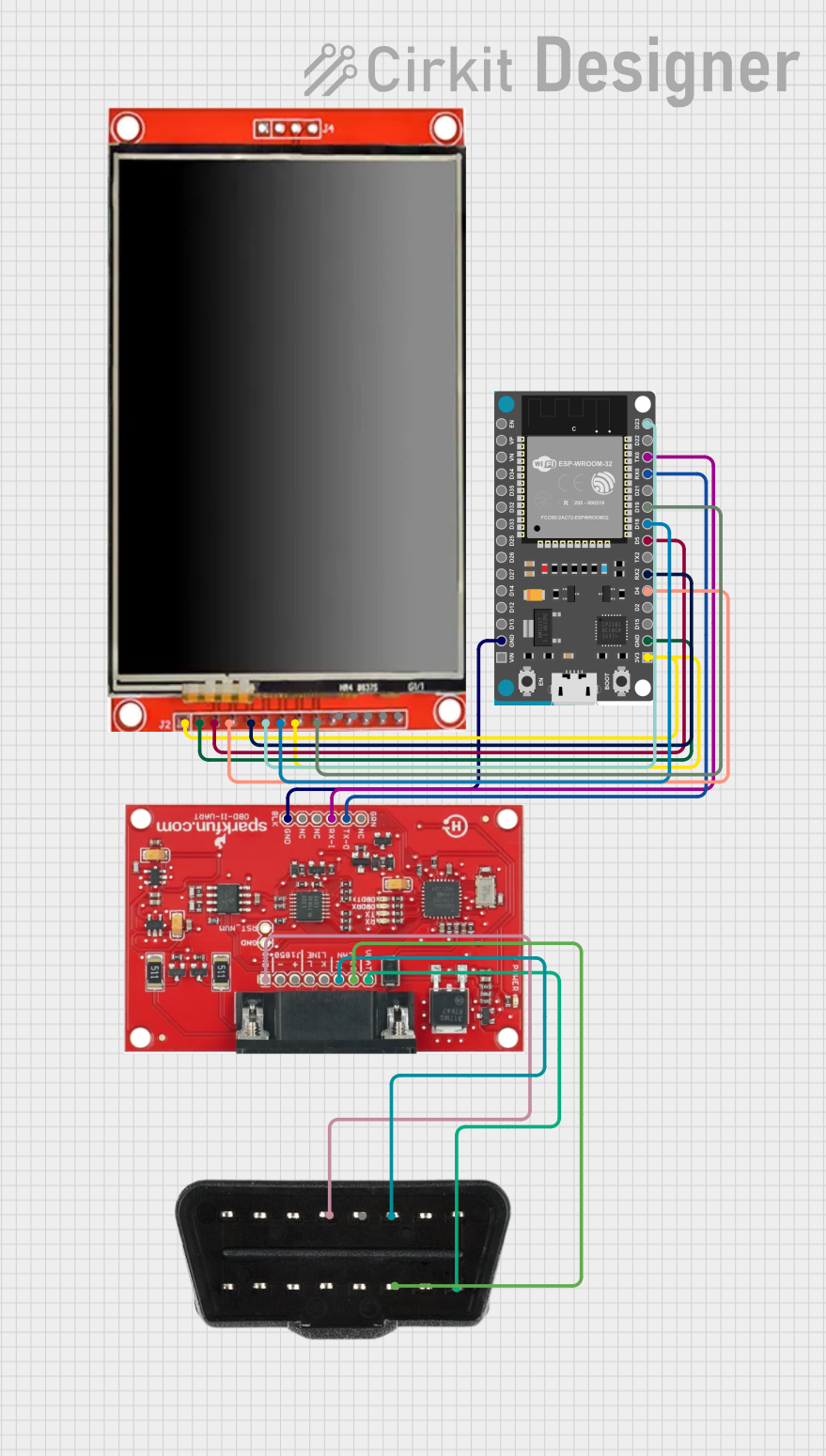
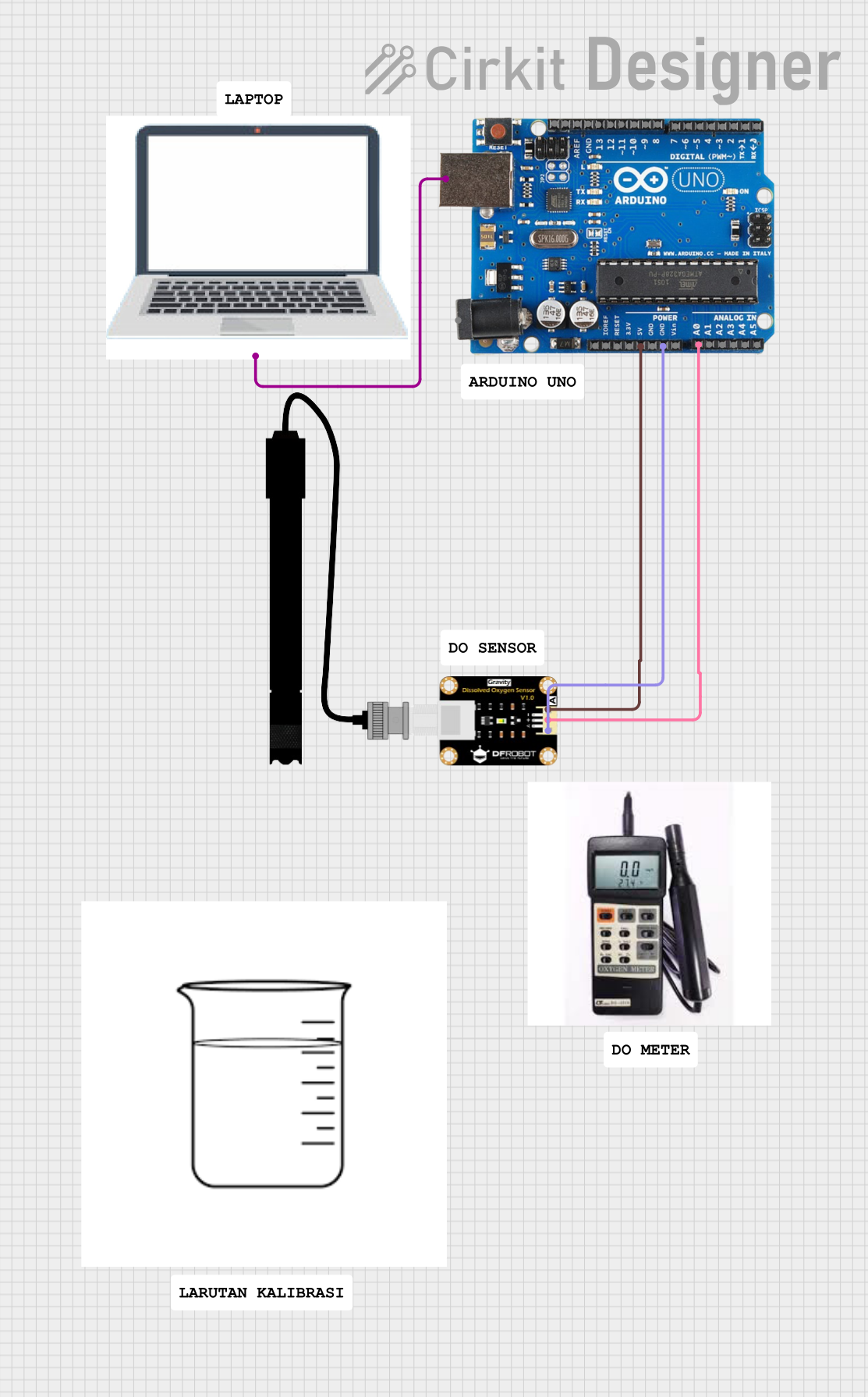
Explore Projects Built with OBD-II port
Common Applications and Use Cases
- Vehicle diagnostics and repair
- Performance tuning
- Fleet management
- Emissions testing
- Insurance telematics
- Data logging for vehicle performance analysis
Technical Specifications
Key Technical Details
- Protocol Support: ISO 9141-2, ISO 14230-4 (KWP2000), ISO 15765-4 (CAN), SAE J1850 PWM, SAE J1850 VPW
- Operating Voltage: 12V (Provided by the vehicle's battery)
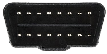
- Data Link Connector Type: J1962
- Pin Configuration: 16 pins
Pin Configuration and Descriptions
| Pin Number | Description | Protocol Support |
|---|---|---|
| 1 | Manufacturer discretion | OEM |
| 2 | SAE J1850 Line (Bus+ Line of PWM) | SAE J1850 PWM |
| 3 | Manufacturer discretion | OEM |
| 4 | Chassis ground | All |
| 5 | Signal ground | All |
| 6 | CAN High (J-2284) | ISO 15765-4 CAN |
| 7 | ISO 9141-2 K Line | ISO 9141-2, ISO 14230-4 |
| 8 | Manufacturer discretion | OEM |
| 9 | Manufacturer discretion | OEM |
| 10 | SAE J1850 Line (Bus- Line of PWM) | SAE J1850 PWM |
| 11 | Manufacturer discretion | OEM |
| 12 | Manufacturer discretion | OEM |
| 13 | Manufacturer discretion | OEM |
| 14 | CAN Low (J-2284) | ISO 15765-4 CAN |
| 15 | ISO 9141-2 L Line | ISO 9141-2, ISO 14230-4 |
| 16 | Battery power | All |
Usage Instructions
How to Use the OBD-II Port in a Circuit
- Locate the OBD-II Port: It is typically found under the dashboard on the driver's side of the vehicle.
- Connect the OBD-II Interface: Use an OBD-II scanner or a compatible device to connect to the port.
- Power Up: The device should power up using the vehicle's battery once connected.
- Establish Communication: The device will attempt to communicate with the vehicle's computer system using one of the supported protocols.
- Data Retrieval: Once a connection is established, you can retrieve diagnostic codes, real-time data, and other vehicle information.
Important Considerations and Best Practices
- Always turn off the vehicle's engine before connecting or disconnecting any devices to the OBD-II port.
- Ensure that the OBD-II device you are using is compatible with the vehicle's protocol.
- Be cautious when using devices that can write data to the vehicle's computer, as incorrect programming can lead to vehicle malfunctions.
- For Arduino and similar hobbyist projects, ensure that you use a proper OBD-II to UART interface module that safely converts signals for microcontroller use.
Troubleshooting and FAQs
Common Issues Users Might Face
- Device Not Recognized: Ensure that the connections are secure and the device is compatible with the vehicle's OBD-II protocol.
- No Power to the Device: Check if the vehicle's battery is charged and the ignition is in the ON position.
- Inaccurate Data: Verify that the device is properly initialized and there are no loose connections.
Solutions and Tips for Troubleshooting
- If the device is not recognized, try using it with another vehicle to rule out device malfunction.
- Check the OBD-II port for any physical damage or debris that may hinder the connection.
- Consult the device's manual for specific troubleshooting steps related to the model.
FAQs
Q: Can I use the OBD-II port to modify my vehicle's performance? A: Yes, but it should be done with caution and typically requires specialized tuning devices or software.
Q: Is it safe to leave an OBD-II device connected at all times? A: While many devices are designed for continuous use, it is important to ensure they do not drain the vehicle's battery.
Q: How do I know which protocol my vehicle uses? A: The vehicle's manual often specifies the protocol. Otherwise, most OBD-II devices automatically detect the correct protocol.
Example Arduino Code
Below is an example of Arduino code to read data from the OBD-II port using an ELM327 OBD-II to UART interface. This code is for demonstration purposes and may require adjustments based on your specific setup and vehicle protocol.
#include <SoftwareSerial.h>

// Initialize the OBD-II UART interface with RX and TX pins
SoftwareSerial obd(10, 11); // RX, TX

void setup() {
  // Start the serial communication
  Serial.begin(9600);
  obd.begin(38400); // The baud rate for ELM327 is typically 38400
  Serial.println("OBD-II Test");
}

void loop() {
  // Send a command to the OBD-II interface
  obd.println("010C"); // This command requests the engine RPM
  delay(100); // Wait for the response

  // Read the response from the OBD-II interface
  if (obd.available()) {
    String data = obd.readString();
    Serial.print("Received data: ");
    Serial.println(data);
  }

  delay(1000); // Wait before sending the next command
}
Remember to wrap the comments in the code to ensure they do not exceed 80 characters in line length.