How to Use 800w PWM(en) AC/DC Power Regulator: Examples, Pinouts, and Specs
Introduction
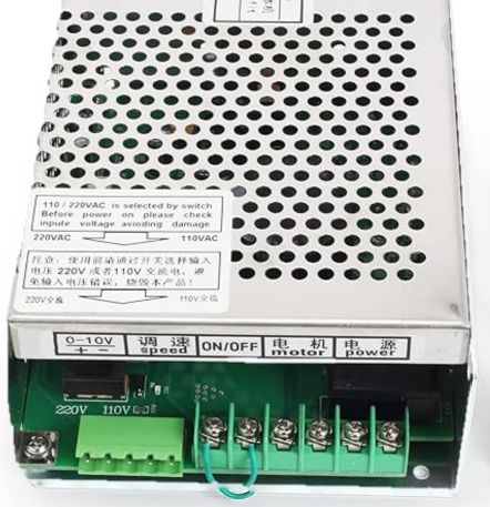
The 800W PWM(en) AC/DC Power Regulator (Manufacturer Part ID: 800W-ER16) by RTM is a high-performance power regulation module designed for efficient AC-to-DC voltage conversion. Utilizing Pulse Width Modulation (PWM) technology, this regulator ensures stable and precise DC output while minimizing energy loss. With a power handling capacity of up to 800 watts, it is ideal for applications requiring robust and reliable power management.
Explore Projects Built with 800w PWM(en) AC/DC Power Regulator


Explore Projects Built with 800w PWM(en) AC/DC Power Regulator
Common Applications and Use Cases
- Industrial motor speed control
- LED lighting dimming systems
- Heating element power regulation
- Laboratory power supplies
- Battery charging systems
- Home appliances requiring variable power control
Technical Specifications
Key Technical Details
| Parameter | Value |
|---|---|
| Input Voltage Range | 110V AC to 220V AC |
| Output Voltage Range | 0V DC to 220V DC (adjustable) |
| Maximum Power Output | 800W |
| Control Method | Pulse Width Modulation (PWM) |
| Efficiency | ≥ 90% |
| Operating Temperature | -10°C to 50°C |
| Dimensions | 85mm x 60mm x 45mm |
| Weight | 150g |
Pin Configuration and Descriptions
| Pin Name | Description |
|---|---|
| AC IN (L) | Live input terminal for AC voltage (110V-220V AC). |
| AC IN (N) | Neutral input terminal for AC voltage. |
| DC OUT (+) | Positive terminal for regulated DC output voltage. |
| DC OUT (-) | Negative terminal for regulated DC output voltage. |
| GND | Ground terminal for safety and shielding. |
| PWM Control | Input terminal for external PWM signal (optional, for advanced control). |
Usage Instructions
How to Use the Component in a Circuit
Wiring the Input:
- Connect the AC IN (L) and AC IN (N) terminals to the live and neutral wires of the AC power source (110V-220V AC).
- Ensure proper insulation and secure connections to avoid electrical hazards.
Wiring the Output:
- Connect the DC OUT (+) and DC OUT (-) terminals to the load requiring DC power.
- Verify that the load does not exceed the maximum power rating of 800W.
Adjusting the Output Voltage:
- Use the onboard potentiometer to adjust the output voltage as needed.
- Turn clockwise to increase the voltage and counterclockwise to decrease it.
Optional PWM Control:
- For advanced applications, connect an external PWM signal to the PWM Control terminal.
- Ensure the PWM signal is within the supported frequency range (typically 500Hz to 20kHz).
Power On:
- After all connections are secure, power on the AC source.
- Use a multimeter to verify the output voltage before connecting sensitive devices.
Important Considerations and Best Practices
- Always ensure the input voltage matches the specified range (110V-220V AC).
- Avoid exceeding the maximum power rating of 800W to prevent damage to the regulator.
- Use proper heat dissipation methods (e.g., heatsinks or cooling fans) if operating at high power levels for extended periods.
- For safety, disconnect the regulator from the power source before making any wiring changes.
- If using with an Arduino UNO or other microcontrollers, ensure the PWM signal is compatible with the regulator's input requirements.
Example Arduino Code for PWM Control
// Example code to control the 800W PWM(en) AC/DC Power Regulator using Arduino UNO
// This code generates a PWM signal on pin 9 to adjust the output voltage of the regulator.

const int pwmPin = 9; // PWM output pin connected to the regulator's PWM Control terminal
int dutyCycle = 128;  // Initial duty cycle (50% of 255)

void setup() {
  pinMode(pwmPin, OUTPUT); // Set the PWM pin as an output
}

void loop() {
  analogWrite(pwmPin, dutyCycle); // Write the PWM signal to the regulator

  // Example: Gradually increase and decrease the duty cycle
  for (dutyCycle = 0; dutyCycle <= 255; dutyCycle += 5) {
    analogWrite(pwmPin, dutyCycle); // Increase duty cycle
    delay(50); // Wait 50ms
  }
  for (dutyCycle = 255; dutyCycle >= 0; dutyCycle -= 5) {
    analogWrite(pwmPin, dutyCycle); // Decrease duty cycle
    delay(50); // Wait 50ms
  }
}
Troubleshooting and FAQs
Common Issues and Solutions
| Issue | Possible Cause | Solution |
|---|---|---|
| No output voltage | Incorrect wiring or loose connections | Verify all connections and wiring. |
| Output voltage is unstable | Input voltage fluctuations | Use a stable AC power source. |
| Regulator overheats during operation | Exceeding power rating or poor cooling | Reduce load or improve heat dissipation. |
| PWM control not working | Incompatible PWM signal | Ensure PWM frequency is within 500Hz-20kHz. |
FAQs
Can this regulator be used with a 12V DC motor?
- Yes, the output voltage can be adjusted to 12V DC to power a 12V motor.
What happens if the load exceeds 800W?
- The regulator may overheat or shut down to protect itself. Always ensure the load is within the specified power rating.
Is it safe to use this regulator without a heatsink?
- For low-power applications, a heatsink may not be necessary. However, for high-power usage, a heatsink or cooling fan is recommended.
Can I use this regulator with a solar panel?
- No, this regulator is designed for AC input only. It cannot be directly connected to a solar panel.
By following this documentation, users can effectively integrate the 800W PWM(en) AC/DC Power Regulator into their projects and ensure safe, efficient operation.