How to Use AC PLUG: Examples, Pinouts, and Specs
AC Plug Documentation
Manufacturer: AC
Part ID: PLUG
1. Introduction
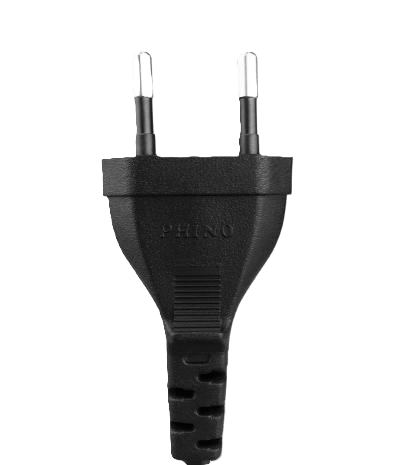
An AC Plug is a device designed to connect electrical appliances to an alternating current (AC) power supply. It typically features prongs or pins that fit into a corresponding socket, enabling the transfer of electrical power. AC plugs are essential components in household, industrial, and commercial electrical systems, ensuring a safe and reliable connection to the power grid.
Common Applications and Use Cases
- Household Appliances: Powering devices such as refrigerators, televisions, and washing machines.
- Industrial Equipment: Connecting machinery and tools to the power supply.
- Portable Electronics: Charging laptops, mobile devices, and other gadgets.
- Lighting Systems: Supplying power to lamps, LED lights, and other fixtures.
2. Technical Specifications
The following table outlines the key technical details of the AC Plug:
| Parameter | Specification |
|---|---|
| Voltage Rating | 110V - 250V AC |
| Current Rating | 10A - 16A |
| Frequency | 50Hz / 60Hz |
| Material | Thermoplastic or thermoset polymer |
| Number of Prongs | 2 or 3 (depending on grounding) |
| Grounding Support | Yes (for 3-prong plugs) |
| Operating Temperature | -20°C to 70°C |
| Safety Standards | IEC 60884-1, UL 498 |
Pin Configuration and Descriptions
| Pin | Description |
|---|---|
| Line (L) | Carries the live AC voltage. |
| Neutral (N) | Returns current to the power source. |
| Ground (G) | Provides a safety path for leakage current (optional). |
3. Usage Instructions
How to Use the AC Plug in a Circuit
- Inspect the Plug: Ensure the AC plug is free from damage, such as cracks or exposed wires.
- Connect Wires:
- Strip the insulation from the wires of the appliance cable.
- Connect the Line (L) wire (usually brown or black) to the live pin.
- Connect the Neutral (N) wire (usually blue or white) to the neutral pin.
- If the plug has a ground pin, connect the Ground (G) wire (usually green or green-yellow).
- Secure the Connections: Tighten the screws on the plug to hold the wires firmly in place.
- Assemble the Plug: Close the plug housing and secure it with screws.
- Test the Connection: Plug the device into a socket and verify that it powers on correctly.
Important Considerations and Best Practices
- Voltage Compatibility: Ensure the plug matches the voltage rating of the power supply.
- Grounding: Always use a grounded plug for devices with metal enclosures to prevent electric shock.
- Wire Gauge: Use wires with an appropriate gauge to handle the current rating of the plug.
- Safety Standards: Only use plugs that comply with relevant safety certifications (e.g., IEC, UL).
4. Troubleshooting and FAQs
Common Issues and Solutions
| Issue | Possible Cause | Solution |
|---|---|---|
| Device does not power on | Loose wire connections in the plug | Recheck and tighten all connections. |
| Sparks when plugging in | Faulty socket or damaged plug | Replace the socket or plug. |
| Overheating of the plug | Overloaded circuit or poor connections | Reduce load or check wire connections. |
| Ground pin not working | Improper grounding or broken pin | Verify grounding and replace the plug. |
Frequently Asked Questions
Q1: Can I use an AC plug rated for 110V in a 220V system?
A1: No, always use a plug rated for the voltage of your power supply to avoid damage or hazards.
Q2: How do I identify the Line, Neutral, and Ground wires?
A2: Wire colors typically follow these conventions:
- Line (L): Brown or Black
- Neutral (N): Blue or White
- Ground (G): Green or Green-Yellow
Q3: Can I use an AC plug without a ground pin?
A3: Yes, but only for devices that are double-insulated and do not require grounding.
Q4: What should I do if the plug gets hot during use?
A4: Stop using the plug immediately. Check for loose connections or an overloaded circuit.
5. Example Application with Arduino UNO
While an AC plug is not directly connected to an Arduino UNO, it can be used to power devices controlled by the Arduino. For example, you can use an AC plug to supply power to a relay module, which the Arduino can control to switch an AC appliance on or off.
Example: Controlling an AC Lamp with Arduino and a Relay
Components Required:
- AC Plug
- Relay Module
- Arduino UNO
- AC Lamp
- Jumper Wires
Circuit Diagram:
Connect the components as follows:
- Connect the AC plug to the input terminals of the relay module.
- Connect the AC lamp to the output terminals of the relay module.
- Connect the relay module's control pins to the Arduino UNO (e.g., IN to pin 7, VCC to 5V, GND to GND).
Arduino Code:
// Example code to control an AC lamp using a relay and Arduino UNO

const int relayPin = 7; // Pin connected to the relay module

void setup() {
  pinMode(relayPin, OUTPUT); // Set relay pin as output
  digitalWrite(relayPin, LOW); // Ensure relay is off at startup
}

void loop() {
  digitalWrite(relayPin, HIGH); // Turn on the relay (lamp ON)
  delay(5000); // Keep the lamp ON for 5 seconds
  digitalWrite(relayPin, LOW); // Turn off the relay (lamp OFF)
  delay(5000); // Keep the lamp OFF for 5 seconds
}
Note: Ensure proper isolation between the AC and DC sides of the circuit to avoid electrical hazards.
This documentation provides a comprehensive guide to understanding, using, and troubleshooting the AC Plug. Always prioritize safety and follow local electrical codes when working with AC power.
Explore Projects Built with AC PLUG


Explore Projects Built with AC PLUG