
How to Use SparkFun Max Power IR LED Kit: Examples, Pinouts, and Specs
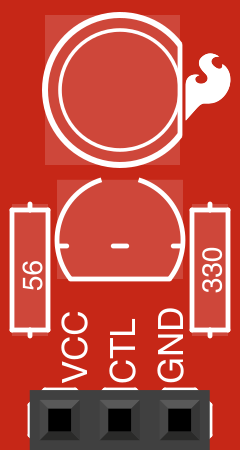
 Design with SparkFun Max Power IR LED Kit in Cirkit Designer
Introduction
The SparkFun Max Power IR LED Kit (Manufacturer Part ID: KIT-10732) is a versatile collection of high-power infrared (IR) LEDs designed for a wide range of applications. These LEDs emit infrared light, which is invisible to the human eye but can be detected by IR receivers, cameras, and other sensors. This kit is ideal for projects requiring IR communication, remote control systems, night vision, or proximity sensing.
Explore Projects Built with SparkFun Max Power IR LED Kit
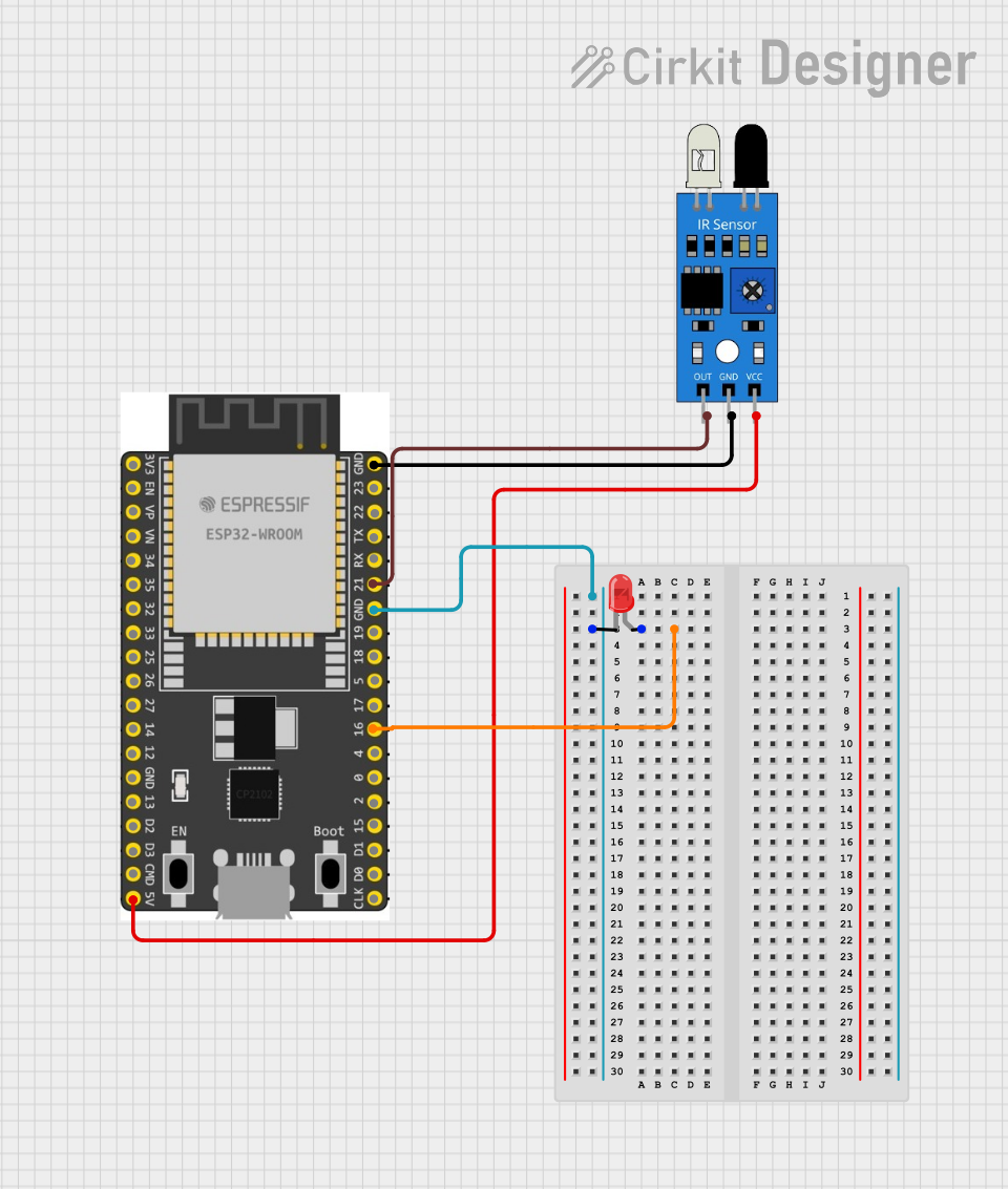 Open Project in Cirkit Designer
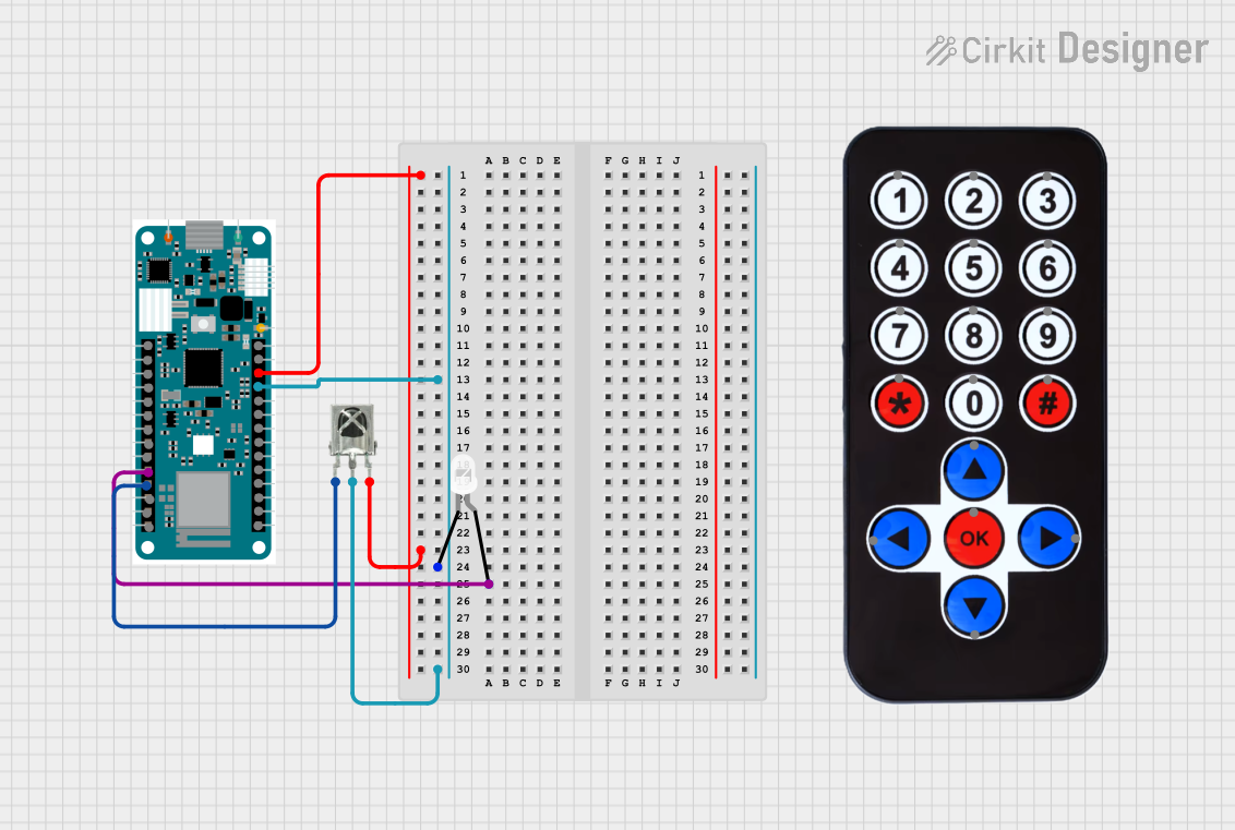 Open Project in Cirkit Designer
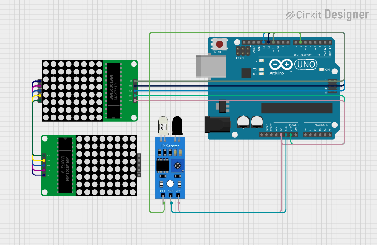 Open Project in Cirkit Designer
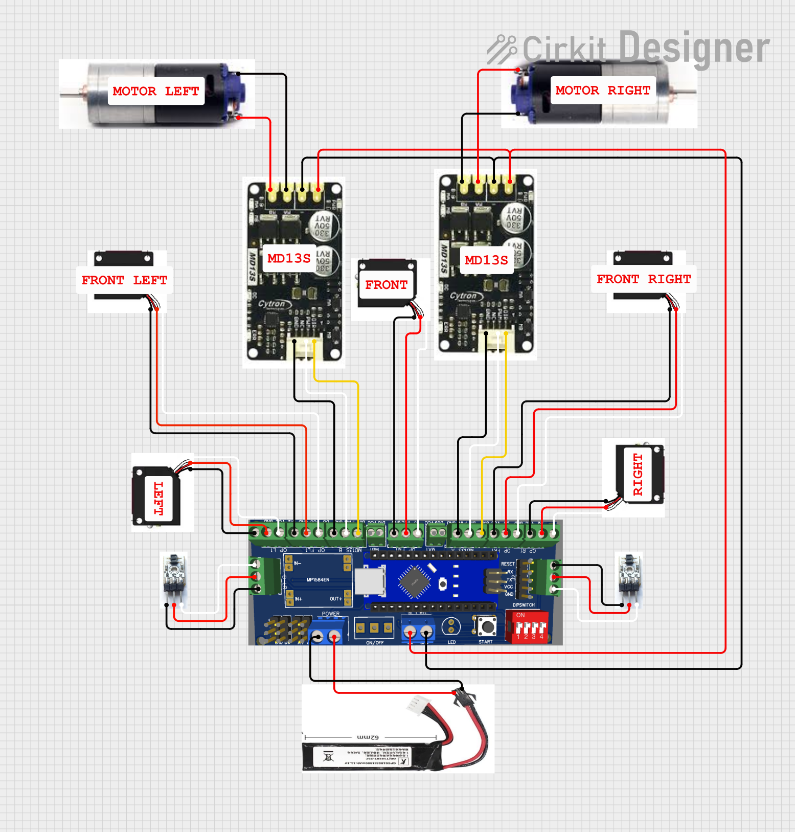 Open Project in Cirkit Designer
Explore Projects Built with SparkFun Max Power IR LED Kit
Open Project in Cirkit DesignerOpen Project in Cirkit DesignerOpen Project in Cirkit DesignerOpen Project in Cirkit DesignerCommon Applications
- Remote Controls: Used in TV remotes, air conditioners, and other consumer electronics.
- IR Communication: Enables data transmission between devices using infrared light.
- Night Vision Systems: Provides illumination for cameras in low-light or no-light environments.
- Proximity Sensors: Detects objects or motion using reflected IR light.
- Robotics: Facilitates obstacle detection and line-following mechanisms.
Technical Specifications
The SparkFun Max Power IR LED Kit includes multiple IR LEDs with varying specifications to suit different project requirements. Below are the general technical details for the LEDs included in the kit:
Key Specifications
| Parameter | Value |
|---|---|
| Wavelength | 850 nm to 950 nm |
| Forward Voltage (Vf) | 1.2V to 1.6V |
| Forward Current (If) | 100 mA to 1 A (depending on LED) |
| Viewing Angle | 20° to 60° |
| Power Output | Up to 100 mW |
| Package Type | Through-hole |
Pin Configuration
Each IR LED in the kit has two pins: Anode (positive) and Cathode (negative). The longer pin is the anode, and the shorter pin is the cathode. Below is a table summarizing the pin configuration:
| Pin Name | Description |
|---|---|
| Anode | Connects to the positive terminal of the power supply. |
| Cathode | Connects to the negative terminal or ground. |
Usage Instructions
How to Use the IR LEDs in a Circuit
- Determine the Forward Voltage and Current: Check the specifications of the specific IR LED you are using from the kit.
- Choose a Resistor: To prevent damage to the LED, calculate the appropriate current-limiting resistor using Ohm's Law:
[
R = \frac{V_{supply} - V_f}{I_f}
]
Where:
- ( V_{supply} ) is the supply voltage.
- ( V_f ) is the forward voltage of the LED.
- ( I_f ) is the desired forward current.
- Connect the LED:
- Connect the anode to the positive terminal of the power supply through the resistor.
- Connect the cathode to the ground.
- Test the Circuit: Power the circuit and use an IR receiver or camera to verify the LED is emitting infrared light.
Important Considerations
- Heat Dissipation: High-power IR LEDs can generate heat. Use appropriate heat sinks or limit the current to prevent overheating.
- Viewing Angle: Choose an LED with the appropriate viewing angle for your application (e.g., narrow for focused beams, wide for general illumination).
- Power Supply: Ensure the power supply can provide sufficient current for the LED without exceeding its maximum rating.
- Polarity: Always connect the anode and cathode correctly to avoid damaging the LED.
Example: Using an IR LED with Arduino UNO
Below is an example of how to use an IR LED from the kit with an Arduino UNO to create a simple IR transmitter:
// Example: IR LED Transmitter with Arduino UNO
// This code blinks an IR LED at a frequency of 38 kHz, commonly used for IR communication.

const int irLedPin = 3; // IR LED connected to digital pin 3

void setup() {
  pinMode(irLedPin, OUTPUT); // Set the IR LED pin as an output
}

void loop() {
  // Emit a 38 kHz signal for 1 second
  for (int i = 0; i < 38000; i++) {
    digitalWrite(irLedPin, HIGH); // Turn the IR LED on
    delayMicroseconds(13);        // 13 microseconds on (half of 38 kHz period)
    digitalWrite(irLedPin, LOW);  // Turn the IR LED off
    delayMicroseconds(13);        // 13 microseconds off
  }
  delay(1000); // Wait for 1 second before repeating
}
Note: Use a current-limiting resistor in series with the IR LED to protect it from excessive current.
Troubleshooting and FAQs
Common Issues
IR LED Not Emitting Light:
- Cause: IR light is invisible to the human eye.
- Solution: Use a camera or IR receiver to verify the LED is functioning.
LED Overheating:
- Cause: Excessive current or insufficient heat dissipation.
- Solution: Use a current-limiting resistor and ensure proper ventilation or heat sinking.
No Signal Detected by IR Receiver:
- Cause: Incorrect frequency or insufficient power.
- Solution: Ensure the IR LED is driven at the correct frequency (e.g., 38 kHz) and verify the circuit connections.
LED Not Turning On:
- Cause: Incorrect polarity or damaged LED.
- Solution: Double-check the anode and cathode connections. Replace the LED if necessary.
FAQs
Q: Can I use the IR LEDs without a resistor?
A: No, using the LEDs without a resistor can result in excessive current flow, damaging the LED.Q: How do I know which wavelength to use?
A: The wavelength depends on your application. For example, 850 nm is suitable for night vision, while 940 nm is commonly used in remote controls.Q: Can I use these LEDs with a 3.3V power supply?
A: Yes, but ensure the forward voltage and current requirements are met by selecting an appropriate resistor.Q: How do I test if the IR LED is working?
A: Use a smartphone camera or digital camera to view the LED while it is powered. The camera will display the IR light as a faint glow.
This concludes the documentation for the SparkFun Max Power IR LED Kit. For additional support, visit the SparkFun Electronics website.