How to Use RAK19001 WisBlock Dual IO Base Board: Examples, Pinouts, and Specs
Introduction
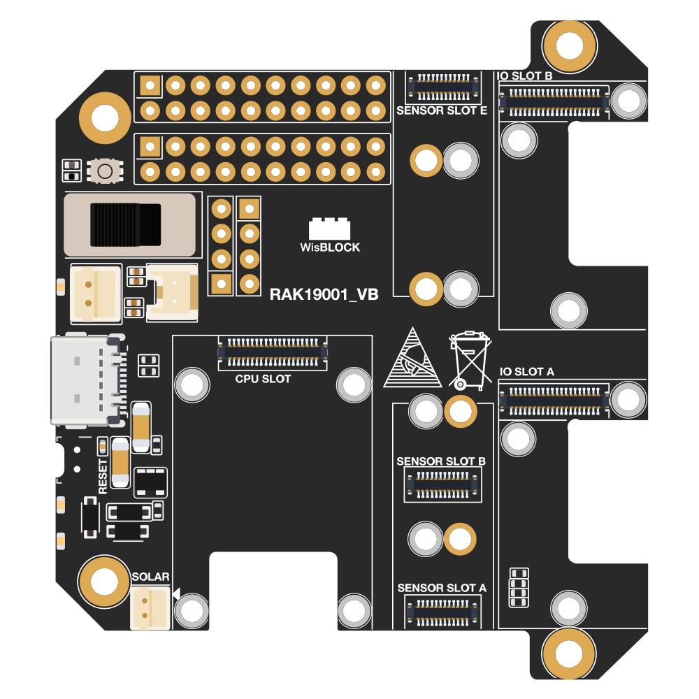
The RAK19001 WisBlock Dual IO Base Board is a modular hardware platform designed by RAK Wireless to simplify the process of building IoT solutions. It serves as a foundation for the WisBlock system, allowing users to connect a WisBlock Core module along with various sensors, peripherals, and devices through its two IO slots. This base board is particularly useful for rapid prototyping and can be used in a wide range of applications, including environmental monitoring, smart agriculture, asset tracking, and more.
Explore Projects Built with RAK19001 WisBlock Dual IO Base Board


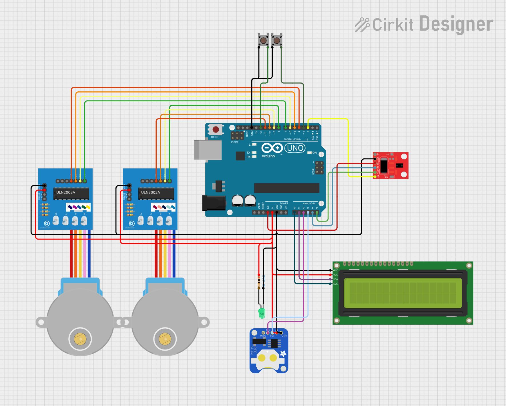
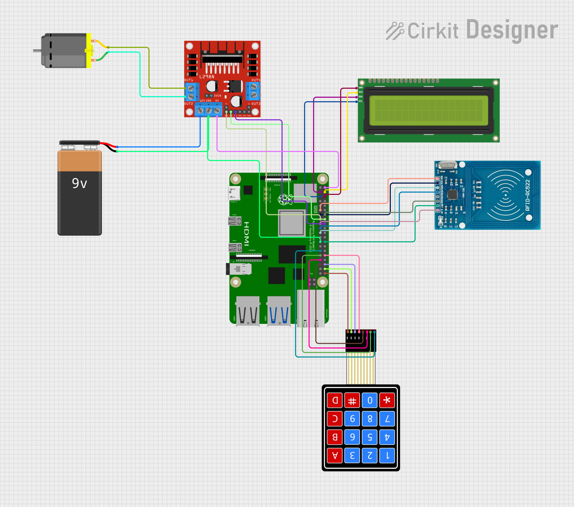
Explore Projects Built with RAK19001 WisBlock Dual IO Base Board
Technical Specifications
Key Technical Details
- Operating Voltage: 3.3V
- Maximum Current: Depends on the connected WisBlock Core and modules
- IO Slots: 2 (compatible with WisBlock modules)
- Dimensions: 60mm x 31mm
- Operating Temperature Range: -40°C to 85°C
Pin Configuration and Descriptions
The RAK19001 provides a variety of connections through its IO slots. Below is a table outlining the pin configuration for these slots.
| Pin Number | Description |
|---|---|
| 1 | GND |
| 2 | 3.3V Power Supply |
| 3 | IO Slot 1 Signal 1 |
| 4 | IO Slot 1 Signal 2 |
| 5 | IO Slot 2 Signal 1 |
| 6 | IO Slot 2 Signal 2 |
| 7 | I2C SDA (Shared) |
| 8 | I2C SCL (Shared) |
| 9 | SPI MOSI (Shared) |
| 10 | SPI MISO (Shared) |
| 11 | SPI SCK (Shared) |
| 12 | SPI NSS (Shared) |
| 13 | UART TX (Shared) |
| 14 | UART RX (Shared) |
| 15 | Analog/Digital GPIO (Shared) |
| 16 | Analog/Digital GPIO (Shared) |
Note: "Shared" indicates that the pin is shared across both IO slots.
Usage Instructions
Connecting to a WisBlock Core
- Select a WisBlock Core: Choose a compatible WisBlock Core module that suits your application's processing requirements.
- Mount the Core: Align the Core module with the connector on the RAK19001 and gently press down to secure it in place.
Adding WisBlock Modules
- Choose WisBlock Modules: Select from a range of compatible modules such as sensors, interface boards, or communication modules.
- Install Modules: Align the connectors of the modules with the IO slots on the RAK19001 and press down to secure them.
Powering the Board
- Supply Power: Provide a 3.3V power supply to the designated pins on the RAK19001. Ensure that the power supply can handle the current requirements of the connected modules.
Programming and Communication
- Connect to a Computer: Use a USB cable to connect the WisBlock Core to a computer for programming.
- Upload Firmware: Utilize the Arduino IDE or other compatible software to upload firmware to the WisBlock Core.
Best Practices
- Check Compatibility: Always ensure that the modules you are connecting are compatible with the RAK19001.
- Avoid Overloading: Do not exceed the current ratings of the power supply and the IO slots.
- Firmware Updates: Keep the firmware of the WisBlock Core and modules up to date for optimal performance.
Troubleshooting and FAQs
Common Issues
- Module Not Recognized: Ensure that the module is properly seated in the IO slot and that there are no bent pins.
- Power Issues: Verify that the power supply is adequate and that all connections are secure.
- Communication Errors: Check the wiring of shared communication pins and ensure there are no conflicts.
FAQs
Q: Can I use any WisBlock Core with the RAK19001? A: The RAK19001 is designed to be compatible with WisBlock Cores. However, always check the specific Core's documentation for compatibility.
Q: How do I know if a module is properly connected? A: A module is properly connected when it is firmly seated in the IO slot without any loose connections.
Q: What should I do if I encounter a problem with the RAK19001? A: Refer to the troubleshooting section, check the RAK Wireless forums, or contact RAK Wireless support for assistance.
Example Code for Arduino UNO
// Example code to initialize communication with a module on the RAK19001
// This example assumes the use of a WisBlock Core compatible with Arduino UNO

#include <Wire.h>

void setup() {
  // Initialize serial communication for debugging
  Serial.begin(115200);

  // Initialize I2C communication
  Wire.begin();

  // TODO: Add module-specific initialization code here
}

void loop() {
  // TODO: Add code to interact with the module(s) connected to the RAK19001

  // Example: Read data from a sensor module
  // byte sensorData = readSensorData();

  // Example: Print data to the serial monitor
  // Serial.println(sensorData);

  // Delay for a moment
  delay(1000);
}

// Function to read data from a sensor (placeholder for actual implementation)
byte readSensorData() {
  // Replace with actual sensor reading code
  return 0;
}
Note: The above code is a generic template and should be modified to suit the specific module and application requirements.
Remember to wrap code comments as needed to limit line length to 80 characters. This ensures readability and maintains a clean, professional appearance in the documentation.