How to Use Arduino Nano ESP32: Examples, Pinouts, and Specs
Introduction
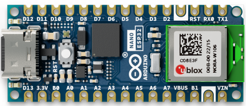
The Arduino Nano ESP32 is a versatile and compact development board that merges the functionality of an Arduino Nano with the advanced features of an ESP32 microcontroller. This board is designed for a wide range of applications, including Internet of Things (IoT) projects, wireless communication, and embedded systems development. With its built-in Wi-Fi and Bluetooth capabilities, the Arduino Nano ESP32 is an excellent choice for hobbyists, educators, and professionals looking to create connected devices with ease.
Explore Projects Built with Arduino Nano ESP32
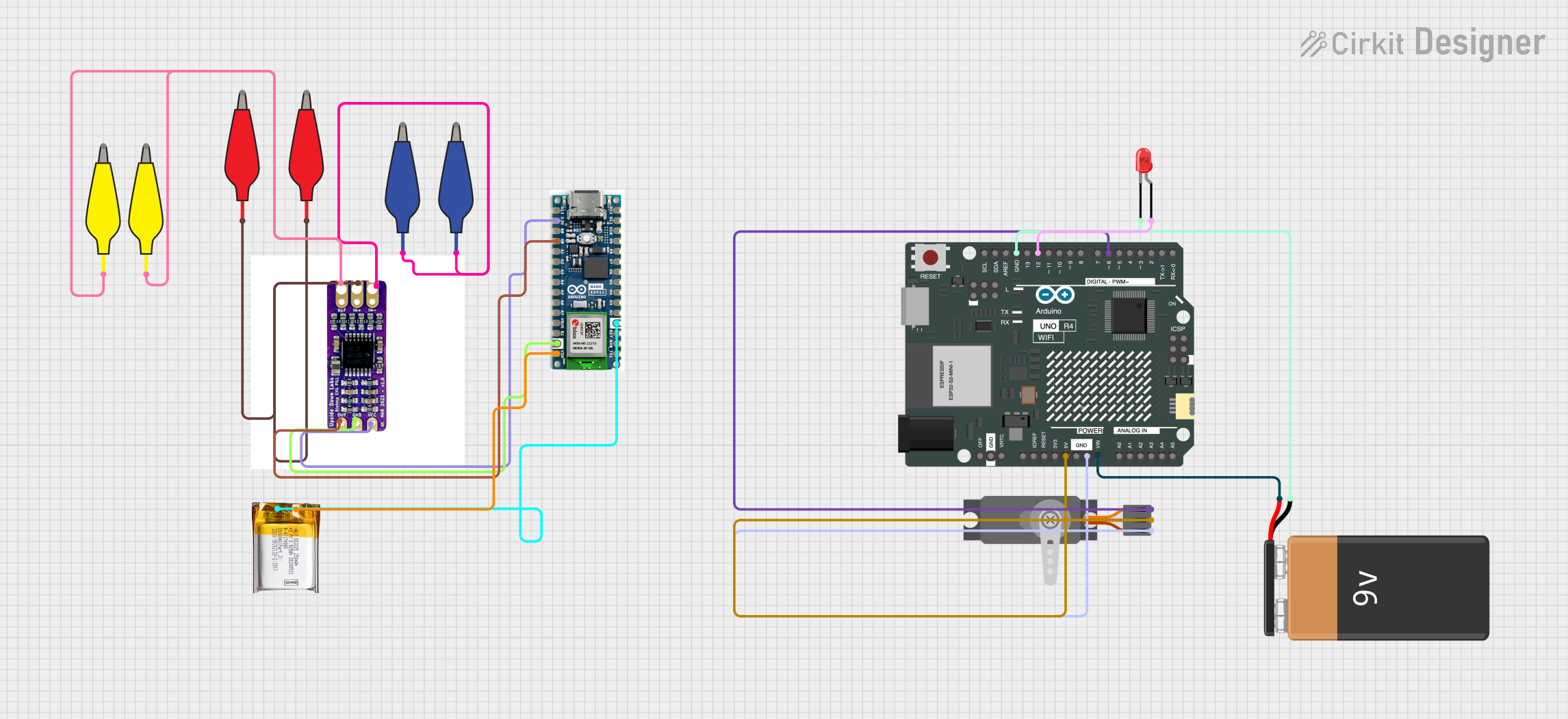
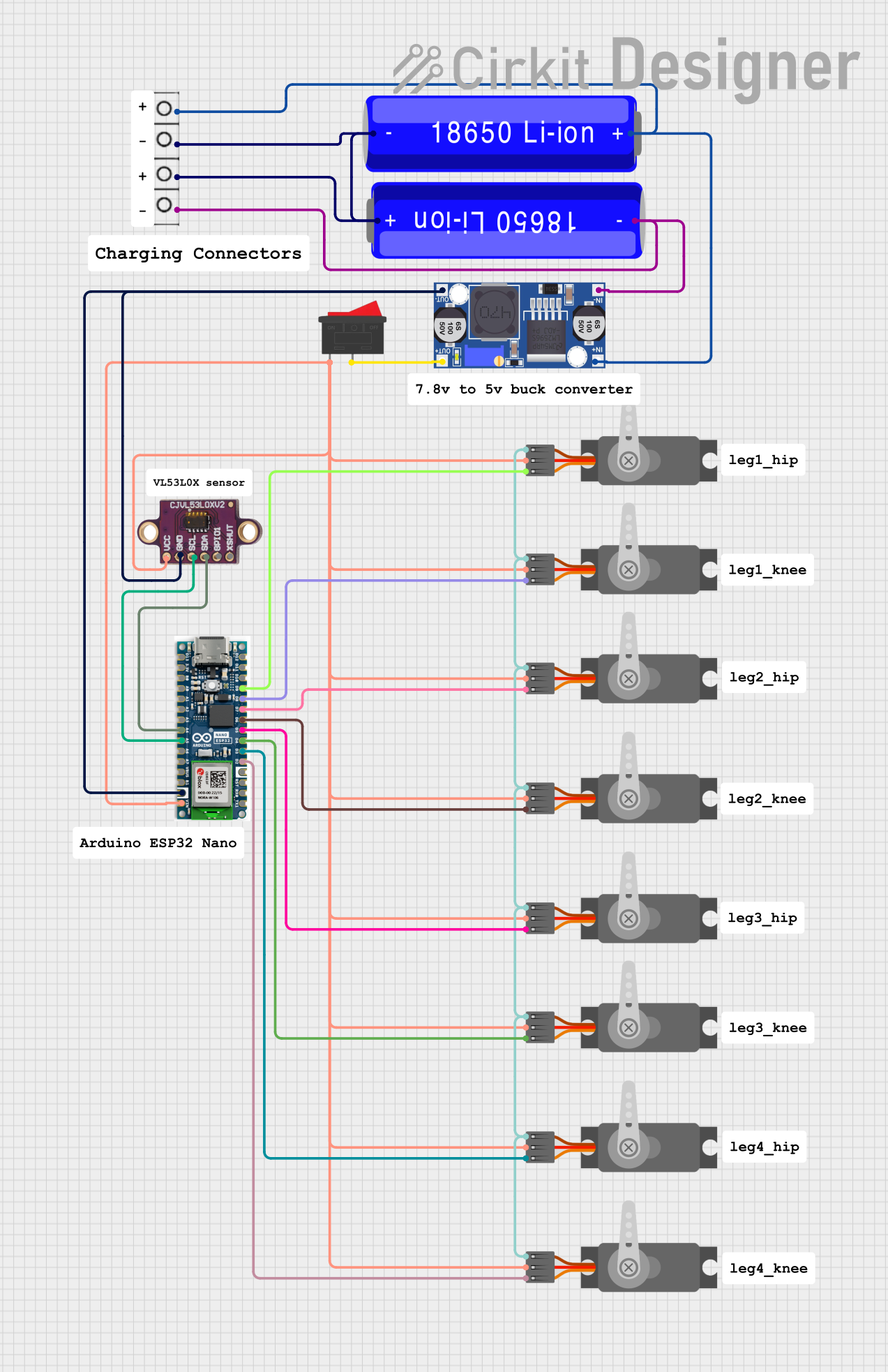
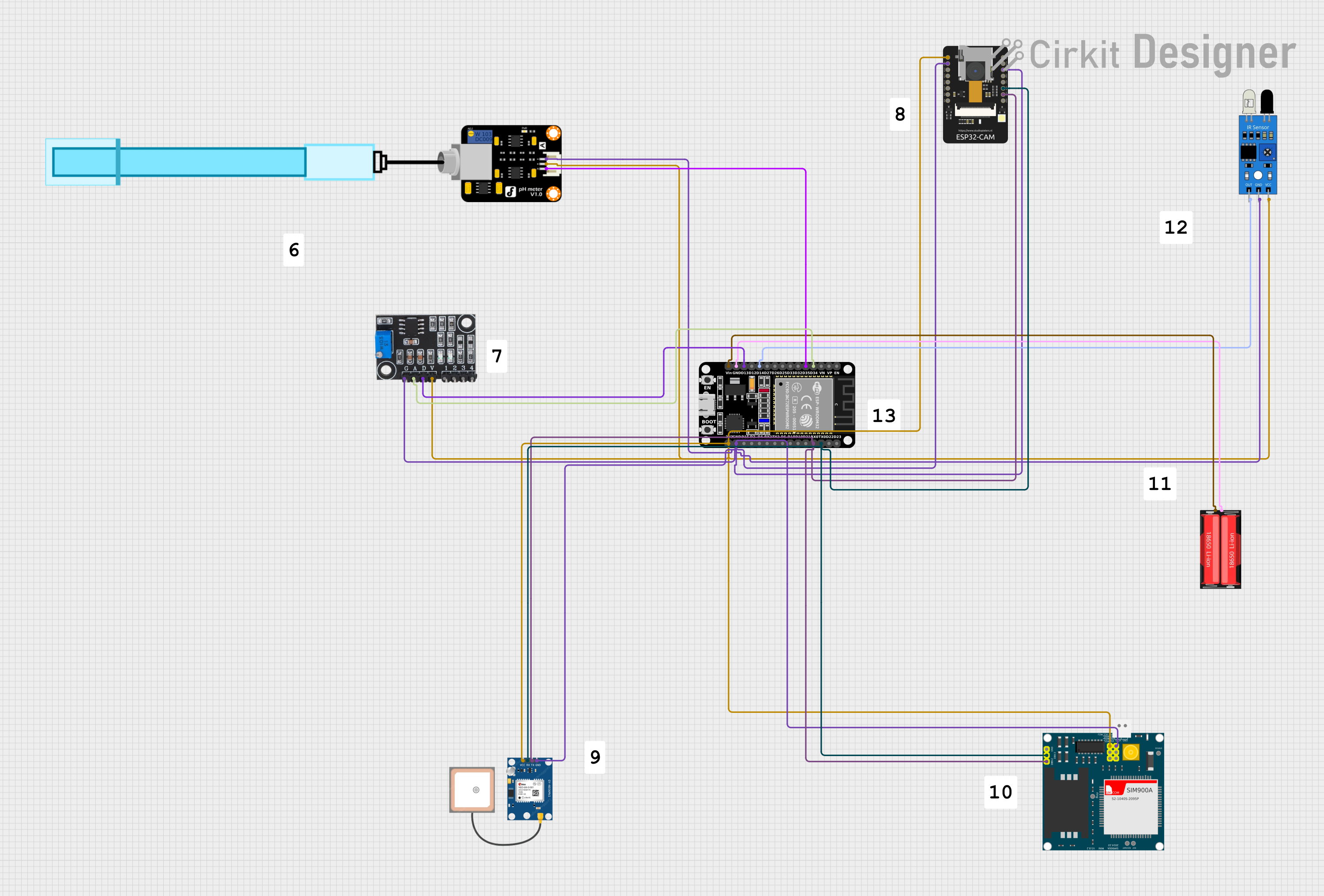
Explore Projects Built with Arduino Nano ESP32
Common Applications and Use Cases
- Smart home devices
- Wireless sensor networks
- IoT prototypes
- Wearable technology
- Remote monitoring and control systems
Technical Specifications
Key Technical Details
- Microcontroller: ESP32
- Operating Voltage: 3.3V
- Input Voltage (recommended): 7-12V
- Input Voltage (limit): 6-20V
- Digital I/O Pins: 14
- Analog Input Pins: 8
- UARTs: 2
- SPIs: 1
- I2Cs: 1
- Flash Memory: 4 MB
- SRAM: 520 KB
- Clock Speed: 240 MHz
- Wi-Fi: 802.11 b/g/n
- Bluetooth: Bluetooth 4.2 and BLE
Pin Configuration and Descriptions
| Pin Number | Function | Description |
|---|---|---|
| 1 | GND | Ground |
| 2 | VIN | Input voltage to the board |
| 3-5 | GND | Ground |
| 6 | 3V3 | 3.3V power output |
| 7-8 | EN / IO0 | Enable pin / Boot mode selection |
| 9-10 | IO34 / IO35 | Analog input pins |
| 11-18 | IO32 / IO33 / IO25 / IO26 / IO27 / IO14 / IO12 / IO13 | General purpose I/O pins |
| 19-20 | IO9 / IO10 | SPI communication pins |
| 21-22 | IO22 / IO1 | I2C communication pins / UART0 TX |
| 23-24 | IO3 / IO21 | UART0 RX / I2C communication pins |
| 25-26 | GND / 5V | Ground / 5V power output |
Usage Instructions
How to Use the Component in a Circuit
Powering the Board:
- Connect a 7-12V power supply to the VIN and GND pins for optimal performance.
- Alternatively, power the board via the USB connection.
Establishing a Connection:
- Use the micro USB port to connect the Arduino Nano ESP32 to a computer for programming.
- Ensure that the correct board and port are selected in the Arduino IDE.
Interfacing with Sensors and Actuators:
- Connect sensors to the analog input pins for data acquisition.
- Use the digital I/O pins to control actuators or read digital sensors.
Wireless Communication:
- Utilize the Wi-Fi and Bluetooth capabilities for wireless projects.
- Follow the ESP32 libraries and examples for setting up network connections.
Important Considerations and Best Practices
- Always disconnect the power source before making or altering connections.
- Use a logic level converter if interfacing with 5V components to prevent damage.
- Avoid exposing the board to static electricity or physical stress.
- Keep the firmware and libraries updated for the latest features and security patches.
Troubleshooting and FAQs
Common Issues Users Might Face
Board not recognized by the computer:
- Check the USB cable and port.
- Ensure that the correct drivers are installed.
Wi-Fi or Bluetooth not functioning:
- Verify that the antennas are properly configured in the code.
- Check for sources of signal interference.
Inconsistent performance or crashes:
- Ensure that the power supply is stable and within the recommended voltage range.
- Check for proper grounding in the circuit.
Solutions and Tips for Troubleshooting
- Reset the board using the EN pin if it becomes unresponsive.
- Use serial debugging to monitor the board's output and diagnose issues.
- Consult the ESP32 datasheet and forums for specific troubleshooting advice.
Example Code for Arduino UNO Connection
#include <WiFi.h>

// Replace with your network credentials
const char* ssid = "your_SSID";
const char* password = "your_PASSWORD";

void setup() {
  Serial.begin(115200);

  // Connect to Wi-Fi
  WiFi.begin(ssid, password);
  while (WiFi.status() != WL_CONNECTED) {
    delay(500);
    Serial.println("Connecting to WiFi...");
  }
  Serial.println("Connected to WiFi");
}

void loop() {
  // Your code here
}
Note: This example demonstrates how to connect the Arduino Nano ESP32 to a Wi-Fi network. Ensure that you replace your_SSID and your_PASSWORD with your actual Wi-Fi network credentials. The serial output can be viewed in the Arduino IDE's Serial Monitor.
For further assistance or questions, refer to the manufacturer's documentation and community forums.