How to Use multimeter: Examples, Pinouts, and Specs
Introduction
A multimeter is a versatile and indispensable tool for anyone working with electronics. It is an electronic measuring instrument that combines multiple measurement functions into a single unit, typically including the ability to measure voltage, current, and resistance. Multimeters are widely used in various applications, from simple home DIY projects to complex industrial electrical systems.
Explore Projects Built with multimeter
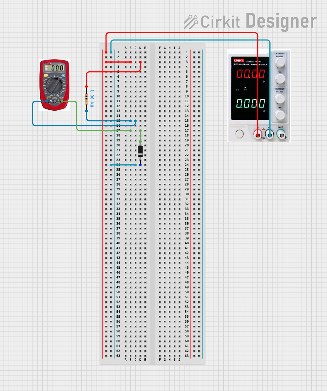
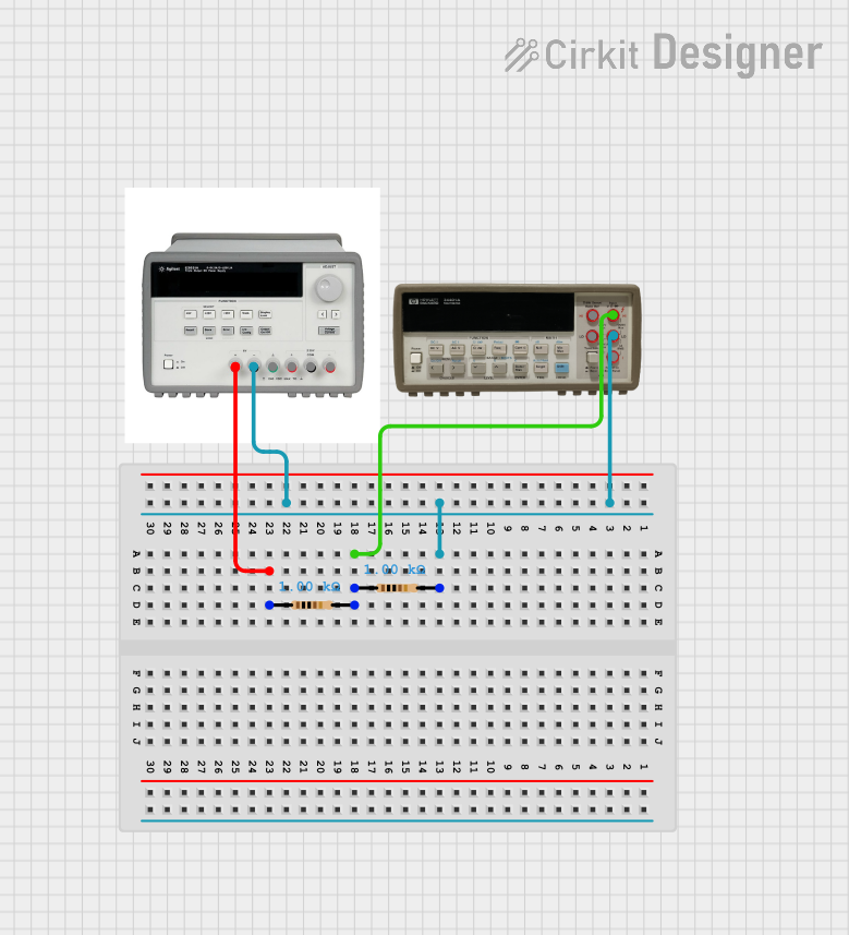
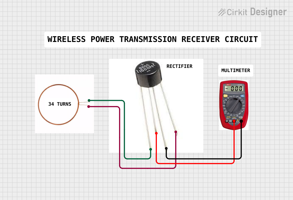
Explore Projects Built with multimeter
Common Applications and Use Cases
- Troubleshooting Electrical Circuits: Identifying faults, checking continuity, and verifying the operation of components.
- Installation and Maintenance: Ensuring proper installation of electrical wiring and hardware, and performing routine checks.
- Educational Purposes: Teaching students about electrical principles and circuit analysis.
- Research and Development: Designing and testing new electronic devices and systems.
- Automotive: Diagnosing electrical issues in vehicles.
Technical Specifications
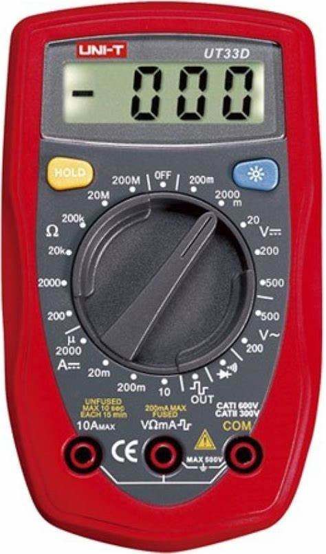
Since a multimeter is not an electronic component but a measurement tool, it does not have a pin configuration. Instead, it has various settings and probes used for different measurements. Below are the key technical details for a typical digital multimeter (DMM):
| Feature | Specification |
|---|---|
| Voltage Range | 0 to 600V AC/DC (may vary by model) |
| Current Range | 0 to 10A AC/DC (may vary by model) |
| Resistance Range | 0 to 60 MΩ (may vary by model) |
| Display | Digital, with a minimum resolution of 0.1 mV |
| Measurement Speed | Updates 2 to 4 times per second |
| Overload Protection | Yes, for all ranges |
| Battery Type | Typically 9V or AA batteries |
| Auto Power Off | To conserve battery life |
| Continuity Test | Audible beep for resistance below a certain threshold (e.g., 50 Ω) |
Usage Instructions
How to Use a Multimeter in a Circuit
Selecting the Measurement Type:
- Turn the multimeter's dial to the desired measurement type (voltage, current, resistance, or continuity).
Connecting the Probes:
- Insert the black probe into the COM (common) jack.
- Insert the red probe into the appropriate jack for the measurement you want to make (e.g., VΩ for voltage or resistance, A for current).
Taking a Measurement:
- For voltage: Touch the probes to the two points in the circuit where you want to measure the voltage difference.
- For current: Break the circuit and insert the multimeter in series so that the current flows through the multimeter.
- For resistance or continuity: Disconnect the power from the circuit and touch the probes to the component or points you want to measure.
Important Considerations and Best Practices
- Always start with the highest range of measurement to prevent damage to the multimeter.
- Ensure the multimeter is rated for the voltage and current levels you expect to measure.
- Never measure resistance or continuity in a live circuit.
- When measuring current, be aware of the maximum current rating of the multimeter to avoid blowing a fuse or damaging the device.
- Always check the multimeter's battery level before use to ensure accurate readings.
Troubleshooting and FAQs
Common Issues
- Inaccurate Readings: This can be due to low battery, incorrect range selection, or damaged probes. Replace the battery, select the correct range, or replace the probes as needed.
- No Reading or OL Displayed: This indicates an overload or out-of-range condition. Select a higher range or check the circuit for faults.
- Multimeter Not Powering On: Check the battery and replace it if necessary. Ensure the battery contacts are clean and making good contact.
Solutions and Tips for Troubleshooting
- If the multimeter does not respond or behaves erratically, reset it by turning it off and on again.
- Regularly check and replace the multimeter's fuses if you frequently measure high currents.
- Keep the multimeter and its probes clean and free from dust and corrosion.
FAQs
Q: Can I use a multimeter to check if a wire is live? A: Yes, you can use the voltage measurement function to check for the presence of voltage in a wire.
Q: How do I know if the fuse in my multimeter is blown? A: If the multimeter does not measure current but other functions work, the fuse may be blown. Check the fuse and replace it if necessary.
Q: What does the 'CAT' rating on my multimeter mean? A: The CAT rating refers to the safety category rating for electrical environments. Higher CAT ratings (e.g., CAT III, CAT IV) indicate the multimeter can safely handle higher energy transients.
Note: This documentation is for a generic digital multimeter and may not cover all features or specifications of specific models or brands. Always refer to the manufacturer's manual for detailed information on your particular multimeter.