How to Use ESP32 DEV KIT V1: Examples, Pinouts, and Specs
Introduction
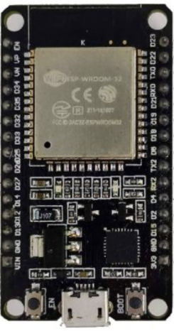
The ESP32 DEV KIT V1 is a versatile development board built around the powerful ESP32 chip. It features integrated Wi-Fi and Bluetooth capabilities, making it an excellent choice for Internet of Things (IoT) applications, smart devices, and rapid prototyping. With its dual-core processor, low power consumption, and extensive GPIO options, the ESP32 DEV KIT V1 is suitable for a wide range of projects, from home automation to wearable technology.
Explore Projects Built with ESP32 DEV KIT V1


Explore Projects Built with ESP32 DEV KIT V1
Common Applications and Use Cases
- IoT devices and smart home systems
- Wireless sensor networks
- Wearable electronics
- Robotics and automation
- Prototyping and educational projects
Technical Specifications
The ESP32 DEV KIT V1 is designed to provide robust performance and flexibility. Below are its key technical specifications:
| Specification | Details |
|---|---|
| Microcontroller | ESP32-D0WDQ6 chip with dual-core Xtensa® 32-bit LX6 processor |
| Clock Speed | Up to 240 MHz |
| Flash Memory | 4 MB (varies by model) |
| SRAM | 520 KB |
| Wi-Fi | 802.11 b/g/n (2.4 GHz) |
| Bluetooth | Bluetooth 4.2 and BLE (Bluetooth Low Energy) |
| Operating Voltage | 3.3V |
| Input Voltage (VIN) | 5V (via USB or external power supply) |
| GPIO Pins | 30 (varies slightly by board version) |
| ADC Channels | 18 (12-bit resolution) |
| DAC Channels | 2 |
| Communication Interfaces | UART, SPI, I2C, I2S, CAN, PWM |
| Power Consumption | Ultra-low power consumption with multiple power modes |
Pin Configuration and Descriptions
The ESP32 DEV KIT V1 features a 30-pin layout. Below is a table describing the key pins:
| Pin | Name | Description |
|---|---|---|
| 1 | VIN | Input voltage (5V) for powering the board |
| 2 | GND | Ground pin |
| 3 | 3V3 | 3.3V output from the onboard voltage regulator |
| 4-21 | GPIO0-GPIO39 | General-purpose input/output pins (various functions like ADC, PWM, etc.) |
| 22 | EN | Enable pin (active high, used to reset the chip) |
| 23 | TXD0 | UART0 transmit pin |
| 24 | RXD0 | UART0 receive pin |
| 25 | ADC1_CH0-CH7 | Analog-to-digital converter channels (12-bit resolution) |
| 26 | DAC1, DAC2 | Digital-to-analog converter channels |
| 27 | BOOT | Boot mode selection pin (used for flashing firmware) |
Usage Instructions
How to Use the ESP32 DEV KIT V1 in a Circuit
Powering the Board:
- Connect the board to a computer or USB power supply using a micro-USB cable.
- Alternatively, supply 5V to the VIN pin and connect GND to the ground.
Programming the Board:
- Install the Arduino IDE and add the ESP32 board support package.
- Select "ESP32 DEV MODULE" from the Tools > Board menu.
- Connect the board to your computer and select the appropriate COM port.
Connecting Peripherals:
- Use the GPIO pins to connect sensors, actuators, or other peripherals.
- Ensure that the voltage levels of connected devices are compatible with the 3.3V logic of the ESP32.
Uploading Code:
- Write your code in the Arduino IDE or another supported environment.
- Click the upload button to flash the code to the ESP32.
Important Considerations and Best Practices
- Voltage Levels: The ESP32 operates at 3.3V logic. Avoid connecting 5V signals directly to GPIO pins.
- Boot Mode: Hold the BOOT button while pressing the EN button to enter firmware flashing mode.
- Power Supply: Ensure a stable power supply to avoid unexpected resets or malfunctions.
- Wi-Fi and Bluetooth: Avoid placing the board near metal objects or enclosures that may interfere with wireless signals.
Example Code for Arduino UNO Integration
Below is an example of using the ESP32 to control an LED via Wi-Fi:
#include <WiFi.h>

// Replace with your network credentials
const char* ssid = "Your_SSID";
const char* password = "Your_PASSWORD";

void setup() {
  Serial.begin(115200); // Initialize serial communication
  pinMode(2, OUTPUT);   // Set GPIO2 (built-in LED) as output

  // Connect to Wi-Fi
  Serial.print("Connecting to Wi-Fi");
  WiFi.begin(ssid, password);
  while (WiFi.status() != WL_CONNECTED) {
    delay(500);
    Serial.print(".");
  }
  Serial.println("\nWi-Fi connected!");
}

void loop() {
  digitalWrite(2, HIGH); // Turn LED on
  delay(1000);           // Wait for 1 second
  digitalWrite(2, LOW);  // Turn LED off
  delay(1000);           // Wait for 1 second
}
Troubleshooting and FAQs
Common Issues and Solutions
Board Not Detected by Computer:
- Ensure the USB cable is functional and supports data transfer.
- Install the correct USB-to-serial driver for your operating system.
Code Upload Fails:
- Check that the correct board and COM port are selected in the Arduino IDE.
- Hold the BOOT button while uploading the code to enter flashing mode.
Wi-Fi Connection Issues:
- Verify the SSID and password in your code.
- Ensure the Wi-Fi network is within range and not using unsupported security protocols.
Random Resets or Instability:
- Use a stable power supply with sufficient current (at least 500mA).
- Avoid connecting high-power peripherals directly to the GPIO pins.
FAQs
Q: Can the ESP32 DEV KIT V1 be powered by a battery?
A: Yes, you can power the board using a 3.7V LiPo battery connected to the 3V3 and GND pins, or a 5V source connected to the VIN pin.
Q: How do I use the Bluetooth functionality?
A: The ESP32 supports both classic Bluetooth and BLE. Use the BluetoothSerial or BLE libraries in the Arduino IDE to implement Bluetooth features.
Q: Can I use the ESP32 with other IDEs?
A: Yes, the ESP32 is compatible with other development environments like PlatformIO, ESP-IDF, and MicroPython.
Q: What is the maximum range of the Wi-Fi module?
A: The Wi-Fi range depends on environmental factors but typically extends up to 50 meters indoors and 200 meters outdoors.