How to Use 12V Relay: Examples, Pinouts, and Specs

Introduction
A 12V relay is an electromechanical switch that allows a low-power circuit to control a separate high-power circuit. It uses an electromagnet to mechanically operate a set of contacts, enabling the control of a wide range of devices such as motors, lights, and other high-current appliances. Relays are commonly used in automotive applications, home automation, industrial controls, and various electronic projects, including those involving Arduino microcontrollers.
Explore Projects Built with 12V Relay

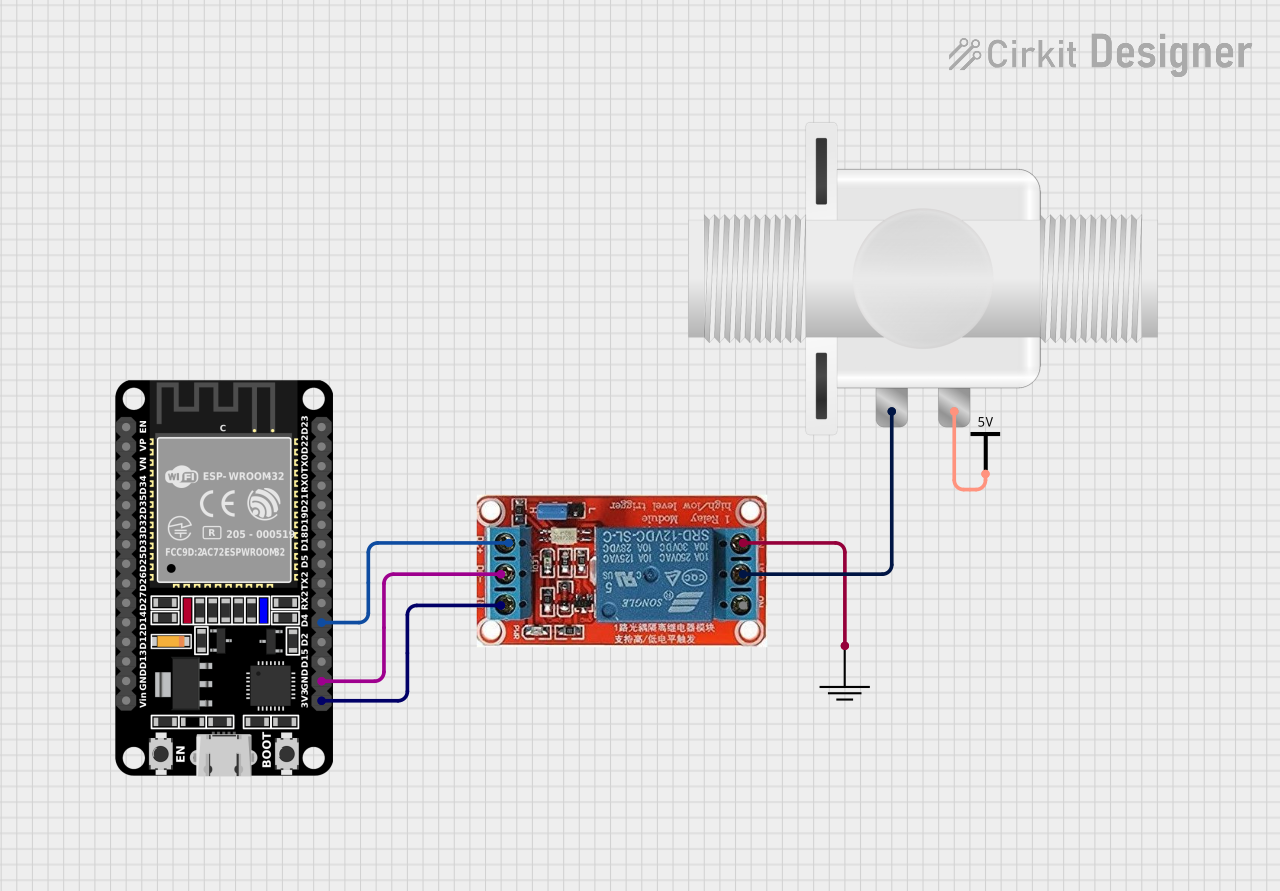

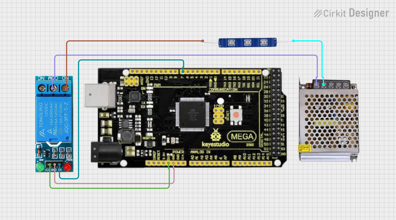
Explore Projects Built with 12V Relay
Technical Specifications
General Features
- Switching Voltage: Up to 250VAC or 30VDC
- Current Rating: Typically 10A
- Coil Voltage: 12VDC
- Coil Current: Varies between 30mA to 100mA
- Contact Configuration: SPDT (Single Pole Double Throw) or DPDT (Double Pole Double Throw)
- Operate/Release Time: Typically 5ms to 20ms
- Electrical Life: 100,000 to 500,000 cycles
Pin Configuration and Descriptions
| Pin Number | Description | Type |
|---|---|---|
| 1 | Coil End 1 | Input |
| 2 | Coil End 2 | Input |
| 3 | Common Contact (COM) | Switch |
| 4 | Normally Closed (NC) | Switch |
| 5 | Normally Open (NO) | Switch |
Note: Pin numbers may vary depending on the relay model. Always refer to the manufacturer's datasheet for exact pin configuration.
Usage Instructions
Wiring the Relay to a Circuit
Powering the Coil:
- Connect the 12V power supply to the coil pins (1 and 2). Polarity is not typically an issue, but check the datasheet for polarity-sensitive relays.
Connecting the Load:
- Connect the device you want to control to the Common (COM) pin (3).
- For a normally open operation, connect the other side of the device to the Normally Open (NO) pin (5).
- For a normally closed operation, connect the other side of the device to the Normally Closed (NC) pin (4).
Driving the Relay with an Arduino:
- Use a digital output pin to control the relay through a transistor, ensuring that the Arduino can supply sufficient current to the relay coil.
- Include a diode in parallel with the relay coil to prevent back EMF from damaging the control circuit.
Best Practices
- Always use a flyback diode across the relay coil to prevent voltage spikes.
- Use a transistor to drive the relay if the control source cannot provide enough current.
- Ensure that the contacts' current and voltage ratings are not exceeded by the controlled circuit.
- Consider using a relay module with built-in driving circuitry for easier interfacing with microcontrollers.
Example Code for Arduino UNO
// Define the relay control pin
const int relayPin = 2;

void setup() {
  // Set the relay pin as an output
  pinMode(relayPin, OUTPUT);
}

void loop() {
  // Turn on the relay (activate the NO contact)
  digitalWrite(relayPin, HIGH);
  delay(1000); // Wait for 1 second

  // Turn off the relay (deactivate the NO contact)
  digitalWrite(relayPin, LOW);
  delay(1000); // Wait for 1 second
}
Note: The above code assumes the use of a relay module that can be driven directly by an Arduino digital output. If using a bare relay, additional circuitry is required to drive the relay coil.
Troubleshooting and FAQs
Common Issues
- Relay not activating: Check the power supply to the coil and ensure the control signal is reaching the relay.
- Intermittent operation: Verify connections and solder joints. Also, check for any signs of contact pitting or burning.
- Clicking sound but no action: The coil is energizing, but the contacts may be damaged or there may be insufficient power to the load.
FAQs
Q: Can I control a 12V relay directly with an Arduino? A: No, an Arduino typically cannot supply enough current to drive a 12V relay coil directly. Use a transistor and a flyback diode.
Q: How do I know if my relay is working? A: You should hear a clicking sound when the relay is activated. You can also use a multimeter to check for continuity across the contacts when the relay is energized.
Q: Can I use a 12V relay with higher voltages? A: You can switch higher voltages within the relay's rated limits, but the coil must be powered with 12V.
Q: Why is my relay generating a lot of heat? A: This could be due to excessive current through the contacts or coil. Ensure the current does not exceed the relay's rating.
For more detailed troubleshooting, always refer to the manufacturer's datasheet and application notes.