How to Use Mini DC-DC 12-24V 3A to 2.5V 3.3V 5V 9V 12V: Examples, Pinouts, and Specs
Introduction
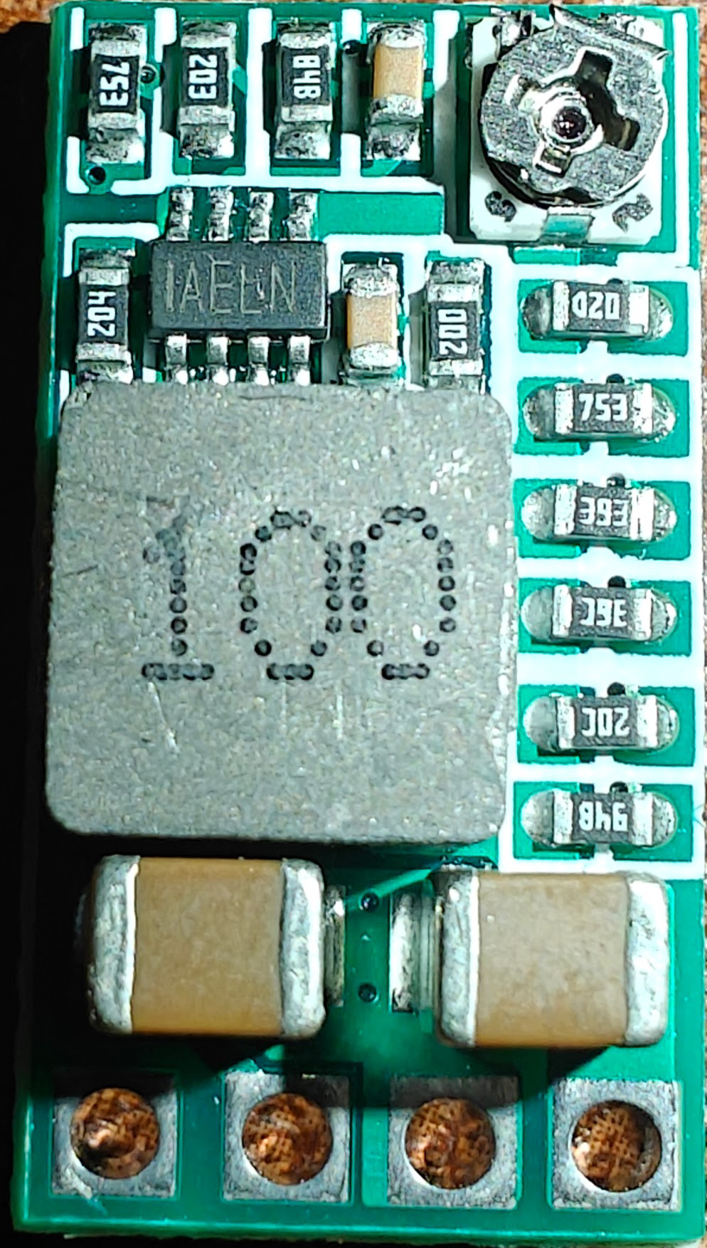
The HiLetgo Mini DC-DC Converter (Part ID: B0CDWW4XHL) is a compact and efficient step-down voltage regulator designed to convert input voltages ranging from 12V to 24V into selectable output voltages of 2.5V, 3.3V, 5V, 9V, or 12V. With a maximum output current of 3A, this module is ideal for powering low-voltage devices such as microcontrollers, sensors, and other electronic components.
Explore Projects Built with Mini DC-DC 12-24V 3A to 2.5V 3.3V 5V 9V 12V


Explore Projects Built with Mini DC-DC 12-24V 3A to 2.5V 3.3V 5V 9V 12V
Common Applications and Use Cases
- Powering microcontrollers (e.g., Arduino, ESP32, Raspberry Pi)
- Supplying regulated voltage to sensors and modules
- Battery-powered systems requiring multiple voltage levels
- DIY electronics projects and prototyping
- Automotive electronics for powering low-voltage devices
Technical Specifications
Key Technical Details
| Parameter | Value |
|---|---|
| Input Voltage Range | 12V to 24V |
| Output Voltage Options | 2.5V, 3.3V, 5V, 9V, 12V (selectable) |
| Maximum Output Current | 3A |
| Efficiency | Up to 95% (depending on input/output ratio) |
| Operating Temperature | -40°C to +85°C |
| Dimensions | 22mm x 17mm x 4mm |
| Weight | ~5g |
Pin Configuration and Descriptions
| Pin Name | Description |
|---|---|
| VIN+ | Positive input voltage terminal (connect to 12-24V DC source) |
| VIN- | Negative input voltage terminal (connect to ground of the DC source) |
| VOUT+ | Positive output voltage terminal (connect to the load's positive terminal) |
| VOUT- | Negative output voltage terminal (connect to the load's ground terminal) |
| Voltage Selector | A small onboard switch or jumper to select the desired output voltage |
Usage Instructions
How to Use the Component in a Circuit
- Input Voltage Connection: Connect the input voltage source (12-24V DC) to the
VIN+andVIN-pins. Ensure the input voltage is within the specified range to avoid damage. - Output Voltage Selection: Use the onboard switch or jumper to select the desired output voltage (2.5V, 3.3V, 5V, 9V, or 12V). Refer to the module's markings for the correct settings.
- Output Voltage Connection: Connect the load to the
VOUT+andVOUT-pins. Ensure the load does not exceed the maximum current rating of 3A. - Power On: Once all connections are secure, power on the input voltage source. The module will regulate the output voltage to the selected level.
Important Considerations and Best Practices
- Heat Dissipation: At higher currents, the module may generate heat. Ensure adequate ventilation or use a heatsink if necessary.
- Input Voltage Range: Do not exceed the 24V input limit, as this may damage the module.
- Output Current Limit: Ensure the connected load does not draw more than 3A to prevent overheating or damage.
- Polarity: Double-check the polarity of the input and output connections to avoid short circuits or damage.
- Voltage Selection: Always confirm the selected output voltage before connecting sensitive devices.
Example: Using with an Arduino UNO
To power an Arduino UNO with 5V using this module:
- Set the output voltage to 5V using the onboard selector.
- Connect the module's
VOUT+to the Arduino's 5V pin andVOUT-to the GND pin. - Connect a 12V DC power source to the module's
VIN+andVIN-.
Here is an example Arduino sketch to blink an LED while powered by the module:
// Simple LED Blink Example
// Ensure the module is set to 5V output before powering the Arduino UNO.

const int ledPin = 13; // Built-in LED pin on Arduino UNO

void setup() {
  pinMode(ledPin, OUTPUT); // Set LED pin as output
}

void loop() {
  digitalWrite(ledPin, HIGH); // Turn the LED on
  delay(1000);               // Wait for 1 second
  digitalWrite(ledPin, LOW);  // Turn the LED off
  delay(1000);               // Wait for 1 second
}
Troubleshooting and FAQs
Common Issues and Solutions
No Output Voltage:
- Verify the input voltage is within the 12-24V range.
- Check all connections for proper polarity and secure contact.
- Ensure the output voltage selector is set correctly.
Overheating:
- Reduce the load current if it exceeds 3A.
- Improve ventilation or add a heatsink to the module.
Incorrect Output Voltage:
- Double-check the voltage selector setting.
- Measure the output voltage with a multimeter to confirm.
Module Not Working:
- Inspect for physical damage or burnt components.
- Ensure the input voltage polarity is correct.
FAQs
Q: Can this module be used with a 9V battery?
A: No, the input voltage must be between 12V and 24V. A 9V battery is insufficient.
Q: Can I use this module to power multiple devices simultaneously?
A: Yes, as long as the total current draw does not exceed 3A.
Q: Is the output voltage stable under varying loads?
A: Yes, the module is designed to provide a stable output voltage with high efficiency.
Q: Can I use this module in automotive applications?
A: Yes, it is suitable for automotive use, provided the input voltage is within the specified range.