How to Use RF 433mhz transmitter: Examples, Pinouts, and Specs
Introduction
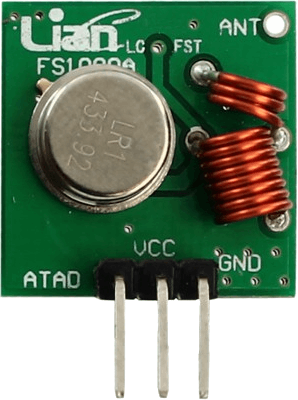
The RF 433MHz transmitter is a compact and efficient device designed to transmit radio frequency signals at 433 MHz. It is widely used in wireless communication systems for low-power applications. This component is ideal for transmitting data over short distances and is commonly paired with an RF 433MHz receiver for complete communication. Its simplicity and low cost make it a popular choice for remote controls, wireless sensors, home automation systems, and other IoT applications.
Explore Projects Built with RF 433mhz transmitter


Explore Projects Built with RF 433mhz transmitter
Common Applications:
- Remote controls for garage doors, fans, and lighting systems
- Wireless weather stations and sensors
- Home automation and IoT devices
- Alarm and security systems
- Data transmission in hobbyist projects
Technical Specifications
The RF 433MHz transmitter is a basic module with the following key specifications:
| Parameter | Value |
|---|---|
| Operating Frequency | 433 MHz |
| Operating Voltage | 3V - 12V |
| Operating Current | 9 mA (typical at 5V) |
| Transmission Range | Up to 100 meters (line of sight) |
| Modulation Type | Amplitude Shift Keying (ASK) |
| Data Rate | Up to 10 kbps |
| Dimensions | ~19mm x 19mm x 7mm |
Pin Configuration and Descriptions
The RF 433MHz transmitter module typically has 4 pins. Below is the pinout and description:
| Pin | Name | Description |
|---|---|---|
| 1 | VCC | Power supply pin. Connect to a voltage source (3V to 12V). |
| 2 | DATA | Data input pin. Connect to the microcontroller or data source. |
| 3 | GND | Ground pin. Connect to the ground of the power supply. |
| 4 | ANT | Antenna pin. Connect to a wire or external antenna for better signal strength. |
Usage Instructions
How to Use the RF 433MHz Transmitter in a Circuit
- Power the Module: Connect the VCC pin to a power source (3V to 12V) and the GND pin to the ground.
- Connect the Data Pin: Attach the DATA pin to the microcontroller or data source. This pin will transmit the digital signal.
- Add an Antenna: For optimal performance, connect a 17 cm wire to the ANT pin. This acts as an antenna and improves the transmission range.
- Pair with a Receiver: Use an RF 433MHz receiver module to receive the transmitted signals.
Important Considerations:
- Power Supply: Ensure the power supply voltage is within the specified range (3V to 12V). Exceeding this range may damage the module.
- Antenna Placement: Place the antenna in an open area, away from metal objects, to maximize the transmission range.
- Data Encoding: Use a library or protocol (e.g., Manchester encoding) to encode the data for reliable transmission.
- Interference: The 433 MHz band is shared by many devices. Minimize interference by testing in a low-noise environment.
Example: Using the RF 433MHz Transmitter with Arduino UNO
Below is an example of how to use the RF 433MHz transmitter with an Arduino UNO to send a simple signal.
Required Components:
- RF 433MHz transmitter module
- Arduino UNO
- 17 cm wire (for the antenna)
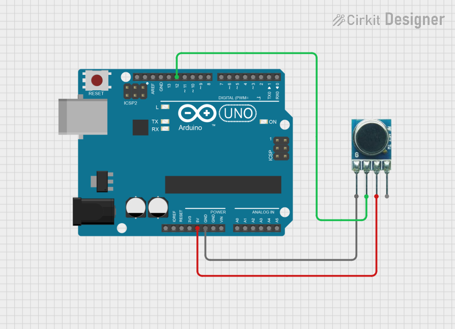
Circuit Diagram:
- Connect the VCC pin of the transmitter to the 5V pin on the Arduino.
- Connect the GND pin of the transmitter to the GND pin on the Arduino.
- Connect the DATA pin of the transmitter to digital pin 10 on the Arduino.
- Attach a 17 cm wire to the ANT pin of the transmitter.
Arduino Code:
// Include the RadioHead library for RF communication
#include <RH_ASK.h>

// Create an instance of the ASK driver
RH_ASK rf_driver;

void setup() {
  // Initialize the RF driver
  if (!rf_driver.init()) {
    // Print an error message if initialization fails
    Serial.println("RF driver initialization failed!");
    while (1); // Halt the program
  }
  Serial.begin(9600); // Start serial communication for debugging
}

void loop() {
  const char *message = "Hello, RF!"; // Message to send
  rf_driver.send((uint8_t *)message, strlen(message)); // Send the message
  rf_driver.waitPacketSent(); // Wait for the message to be sent
  delay(1000); // Wait 1 second before sending the next message
}
Notes:
- Install the
RadioHeadlibrary in the Arduino IDE before uploading the code. - The receiver module should be configured to decode the transmitted signal.
Troubleshooting and FAQs
Common Issues and Solutions:
No Signal Received:
- Ensure the transmitter and receiver are operating at the same frequency (433 MHz).
- Check the antenna connection and placement for both modules.
- Verify the power supply voltage is within the specified range.
Short Transmission Range:
- Use a longer antenna (17 cm is optimal for 433 MHz).
- Reduce interference by moving the module away from other electronic devices.
Data Corruption:
- Use a reliable encoding/decoding library (e.g., RadioHead) to prevent data loss.
- Ensure the data rate does not exceed the module's maximum limit (10 kbps).
Module Overheating:
- Check the power supply voltage. Excessive voltage can cause overheating.
- Avoid continuous transmission for extended periods.
FAQs:
Q: Can I use the RF 433MHz transmitter without an antenna?
A: While it is possible, the transmission range will be significantly reduced. Adding a 17 cm wire as an antenna is highly recommended.
Q: What is the maximum range of the RF 433MHz transmitter?
A: The maximum range is approximately 100 meters in an open, line-of-sight environment. Obstacles and interference can reduce this range.
Q: Can I use multiple transmitters in the same area?
A: Yes, but you should implement a protocol to avoid signal collisions, as the 433 MHz band is shared.
Q: Is the RF 433MHz transmitter compatible with 3.3V microcontrollers?
A: Yes, the module can operate at 3V, making it compatible with 3.3V microcontrollers like the ESP8266 or ESP32.
By following this documentation, you can effectively integrate the RF 433MHz transmitter into your projects for reliable wireless communication.