How to Use UHF RFID IN-R200: Examples, Pinouts, and Specs
Introduction
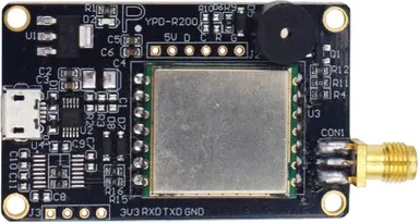
The UHF RFID IN-R200 is an ultra-high frequency (UHF) radio frequency identification (RFID) module designed for wireless data transmission and reception. It operates in the UHF spectrum, typically between 860 MHz to 960 MHz, which allows for long-range communication and high-speed data transfer. This component is commonly used in inventory management, asset tracking, identification, and access control systems.
Explore Projects Built with UHF RFID IN-R200
Explore Projects Built with UHF RFID IN-R200
Common Applications and Use Cases
- Inventory tracking in warehouses
- Asset management in logistics
- Contactless entry systems
- Library book sorting and management
- Race timing systems
- Retail item tracking for smart checkout systems
Technical Specifications
Key Technical Details
- Operating Frequency: 860 MHz to 960 MHz
- Interface: SPI/UART (selectable)
- Supply Voltage: 3.3V to 5V DC
- Operating Current: 30mA (typical)
- Read Range: Up to 5 meters (depending on antenna and environment)
- Antenna Impedance: 50 Ohms
Pin Configuration and Descriptions
| Pin Number | Pin Name | Description |
|---|---|---|
| 1 | VCC | Power supply (3.3V to 5V DC) |
| 2 | GND | Ground |
| 3 | TX | UART Transmit / SPI MOSI |
| 4 | RX | UART Receive / SPI MISO |
| 5 | SCK | SPI Clock |
| 6 | SDA | SPI Data / UART Select |
| 7 | IRQ | Interrupt Request (active low) |
| 8 | GPIO1 | General Purpose Input/Output 1 |
| 9 | GPIO2 | General Purpose Input/Output 2 |
| 10 | ANT | Antenna Connection (50 Ohms impedance) |
Usage Instructions
How to Use the Component in a Circuit
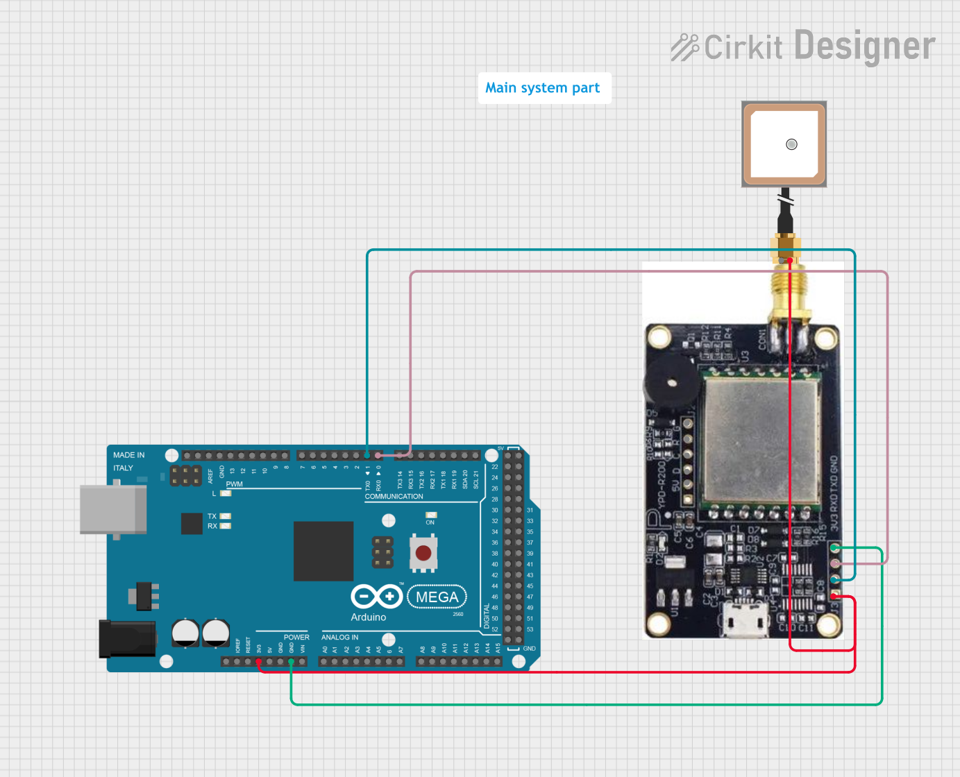
- Power Supply: Connect the VCC pin to a 3.3V to 5V DC power source and the GND pin to the ground of your circuit.
- Data Interface: Choose between UART or SPI for communication with a microcontroller such as an Arduino UNO. For UART, connect the TX and RX pins to the RX and TX pins of the Arduino, respectively. For SPI, connect SCK, SDA, and the SPI select pin to the corresponding SPI pins on the Arduino.
- Antenna: Connect a suitable UHF RFID antenna to the ANT pin to enable communication.
- GPIO (Optional): GPIO1 and GPIO2 can be used for additional functionality as required by your application.
Important Considerations and Best Practices
- Ensure that the power supply is within the specified voltage range to prevent damage.
- Use impedance-matched antennas to maximize read range and reliability.
- Place the RFID antenna away from metal surfaces to avoid interference.
- For optimal performance, avoid physical obstructions between the RFID reader and tags.
- Follow local regulations regarding the use of UHF RFID frequencies.
Troubleshooting and FAQs
Common Issues Users Might Face
- Short Read Range: Ensure that the antenna is properly connected and there are no obstructions or interference from metal objects.
- No Communication: Check the power supply and connections to the microcontroller. Verify that the correct communication protocol (UART or SPI) is selected.
- Intermittent Operation: Inspect the antenna and connections for any loose contacts or damage.
Solutions and Tips for Troubleshooting
- Double-check wiring and solder joints for any faults.
- Use a logic analyzer or oscilloscope to verify communication signals.
- Ensure that the RFID tags are compatible with the UHF frequency range of the reader.
- Test the module with a known good antenna and RFID tag to isolate the issue.
FAQs
Q: Can the UHF RFID IN-R200 be used with an Arduino UNO? A: Yes, it can be interfaced using UART or SPI communication protocols.
Q: What is the maximum read range of the UHF RFID IN-R200? A: The maximum read range is up to 5 meters, but this can vary based on the antenna used and environmental conditions.
Q: Is the UHF RFID IN-R200 compatible with all RFID tags? A: It is compatible with tags that operate within the 860 MHz to 960 MHz UHF range.
Q: How can I increase the read range of the UHF RFID IN-R200? A: Use a high-quality, impedance-matched antenna and ensure there are no obstructions or interference in the environment.
Example Code for Arduino UNO
Below is an example of how to interface the UHF RFID IN-R200 with an Arduino UNO using UART communication. This code initializes the serial communication and waits for data from the RFID reader.
#include <SoftwareSerial.h>

// Define the RX and TX pins connected to the RFID reader
#define RFID_RX_PIN 10 // Connect to TX of RFID reader
#define RFID_TX_PIN 11 // Connect to RX of RFID reader

// Initialize the software serial port
SoftwareSerial rfidSerial(RFID_RX_PIN, RFID_TX_PIN);

void setup() {
  // Start the hardware serial port for debugging
  Serial.begin(9600);
  // Start the software serial port for RFID reader communication
  rfidSerial.begin(9600);
  Serial.println("RFID reader initialized");
}

void loop() {
  // Check if data is available from the RFID reader
  if (rfidSerial.available()) {
    // Read the data and print it to the hardware serial port
    Serial.print(char(rfidSerial.read()));
  }
}
Remember to adjust the pin definitions to match your actual connections. This code is a simple starting point and does not include the full implementation required to decode RFID tag data. Additional libraries and code may be necessary to fully utilize the capabilities of the UHF RFID IN-R200.