How to Use JDY-16: Examples, Pinouts, and Specs
Introduction
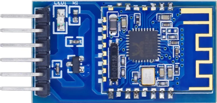
The JDY-16 is a Bluetooth module manufactured by Shenzhen JDY, designed for wireless communication in embedded systems and IoT applications. It supports serial communication (UART) and operates on Bluetooth 4.2 technology, making it ideal for low-power, short-range wireless data transmission. The JDY-16 is widely used due to its compact size, low power consumption, and ease of integration into various projects.
Explore Projects Built with JDY-16


Explore Projects Built with JDY-16
Common Applications and Use Cases
- Wireless data transmission in IoT devices
- Home automation systems
- Remote control and monitoring
- Wireless sensor networks
- Serial communication between microcontrollers and smartphones
Technical Specifications
The JDY-16 module is designed to provide reliable Bluetooth communication with minimal power consumption. Below are its key technical specifications:
| Parameter | Value |
|---|---|
| Bluetooth Version | Bluetooth 4.2 |
| Communication Interface | UART (3.3V logic level) |
| Operating Voltage | 3.3V to 6V |
| Operating Current | 8mA (active), 0.5mA (standby) |
| Transmission Distance | Up to 30 meters (open space) |
| Baud Rate | Default: 9600 bps (configurable) |
| Dimensions | 26mm x 13mm x 2.2mm |
| Operating Temperature | -40°C to +85°C |
Pin Configuration and Descriptions
The JDY-16 module has 6 pins, as described in the table below:
| Pin Number | Pin Name | Description |
|---|---|---|
| 1 | VCC | Power supply input (3.3V to 6V) |
| 2 | GND | Ground |
| 3 | TXD | UART Transmit pin (3.3V logic level) |
| 4 | RXD | UART Receive pin (3.3V logic level) |
| 5 | STATE | Connection status output (HIGH when connected) |
| 6 | EN | Enable pin (active HIGH, used to enable the module) |
Usage Instructions
The JDY-16 module is straightforward to use and can be easily integrated into a circuit for wireless communication. Below are the steps and best practices for using the module:
Connecting the JDY-16 to a Microcontroller
- Power Supply: Connect the
VCCpin to a 3.3V or 5V power source and theGNDpin to ground. - UART Communication:
- Connect the
TXDpin of the JDY-16 to the RX pin of the microcontroller. - Connect the
RXDpin of the JDY-16 to the TX pin of the microcontroller.
- Connect the
- Enable the Module: Pull the
ENpin HIGH to enable the module. - Connection Status: Use the
STATEpin to monitor the connection status (HIGH when connected).
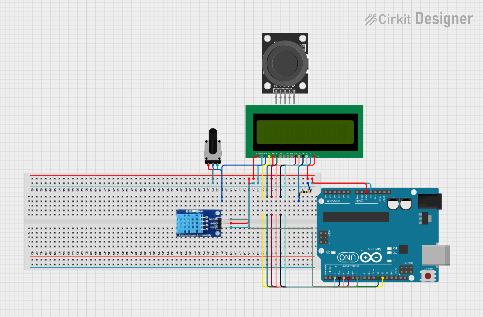
Example: Using JDY-16 with Arduino UNO
The JDY-16 can be connected to an Arduino UNO for wireless communication. Below is an example of how to send and receive data using the module:
Wiring Diagram
| JDY-16 Pin | Arduino UNO Pin |
|---|---|
| VCC | 5V |
| GND | GND |
| TXD | Pin 10 (Software RX) |
| RXD | Pin 11 (Software TX) |
| EN | 3.3V or 5V |
Arduino Code
#include <SoftwareSerial.h>

// Define RX and TX pins for SoftwareSerial
SoftwareSerial JDY16(10, 11); // RX = Pin 10, TX = Pin 11

void setup() {
  // Initialize serial communication
  Serial.begin(9600); // For communication with the PC
  JDY16.begin(9600);  // For communication with the JDY-16 module

  Serial.println("JDY-16 Bluetooth Module Test");
}

void loop() {
  // Check if data is available from the JDY-16 module
  if (JDY16.available()) {
    char data = JDY16.read(); // Read data from JDY-16
    Serial.print("Received: ");
    Serial.println(data);     // Print received data to the Serial Monitor
  }

  // Check if data is available from the Serial Monitor
  if (Serial.available()) {
    char data = Serial.read(); // Read data from the Serial Monitor
    JDY16.write(data);         // Send data to the JDY-16 module
    Serial.print("Sent: ");
    Serial.println(data);      // Print sent data to the Serial Monitor
  }
}
Important Considerations and Best Practices
- Voltage Levels: Ensure the JDY-16's
RXDpin receives a 3.3V logic level. Use a voltage divider or level shifter if connecting to a 5V microcontroller. - Baud Rate: The default baud rate is 9600 bps. Configure the microcontroller's UART to match this baud rate.
- Connection Distance: The module performs best in open spaces with minimal interference.
- Power Supply: Use a stable power source to avoid communication issues.
Troubleshooting and FAQs
Common Issues and Solutions
No Communication with the Module:
- Ensure the
ENpin is pulled HIGH to enable the module. - Verify the wiring of the
TXDandRXDpins. - Check that the baud rate of the microcontroller matches the module's baud rate.
- Ensure the
Unstable Connection:
- Ensure the power supply is stable and within the specified voltage range.
- Minimize interference from other Bluetooth devices or obstacles.
Module Not Discoverable:
- Confirm that the module is powered on and enabled.
- Check the Bluetooth settings on the connecting device.
FAQs
Q: Can the JDY-16 module be configured for a different baud rate?
A: Yes, the baud rate can be configured using AT commands. Refer to the manufacturer's documentation for the complete list of AT commands.
Q: What is the maximum data transmission speed of the JDY-16?
A: The JDY-16 supports a maximum baud rate of 115200 bps.
Q: Can the JDY-16 be used with a 5V microcontroller?
A: Yes, but ensure the RXD pin receives a 3.3V logic level. Use a voltage divider or level shifter if necessary.
Q: How can I reset the JDY-16 module?
A: The module can be reset by cycling the power (disconnecting and reconnecting the VCC pin).