How to Use qwiic multiport: Examples, Pinouts, and Specs
Introduction
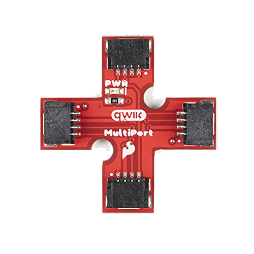
The Qwiic Multiport is a versatile connector designed to simplify the integration of multiple Qwiic-enabled devices in a single I2C communication chain. It provides a convenient way to connect and power multiple devices without the need for soldering or complex wiring. The Qwiic Multiport is ideal for prototyping, educational projects, and any application requiring multiple I2C devices to work together seamlessly.
Explore Projects Built with qwiic multiport

Explore Projects Built with qwiic multiport
Common Applications and Use Cases
- Prototyping with multiple I2C sensors and modules
- Educational projects involving I2C communication
- Robotics and automation systems
- IoT (Internet of Things) devices requiring multiple peripherals
- Simplifying wiring in complex circuits
Technical Specifications
The Qwiic Multiport is designed to work with the Qwiic ecosystem, which uses a standardized 4-pin JST connector for I2C communication. Below are the key technical details:
Key Technical Details
- Voltage Range: 3.3V (standard for Qwiic devices)
- Current Rating: Up to 1A (shared across all connected devices)
- Connector Type: 4-pin JST (Qwiic standard)
- I2C Protocol: Supports standard I2C communication (SCL and SDA lines)
- Dimensions: Varies by model, typically compact for easy integration
- Compatibility: Fully compatible with all Qwiic-enabled devices
Pin Configuration and Descriptions
The Qwiic Multiport features multiple 4-pin JST connectors, all of which are internally connected in parallel. Below is the pinout for each connector:
| Pin Number | Pin Name | Description |
|---|---|---|
| 1 | GND | Ground connection |
| 2 | 3.3V | Power supply (3.3V) |
| 3 | SDA | I2C data line |
| 4 | SCL | I2C clock line |
Usage Instructions
How to Use the Qwiic Multiport in a Circuit
- Connect the Multiport to a Power Source: Ensure the Qwiic Multiport is connected to a 3.3V power source, typically provided by a microcontroller or development board like the Arduino UNO (with a 3.3V regulator).
- Connect Qwiic Devices: Plug Qwiic-enabled devices into the Multiport using Qwiic cables. The Multiport allows multiple devices to share the same I2C bus.
- Address Configuration: Ensure each connected device has a unique I2C address. Refer to the datasheet of each device to configure or check its address.
- Connect to a Microcontroller: Use a Qwiic cable to connect the Multiport to the I2C pins of your microcontroller (e.g., SDA and SCL on the Arduino UNO).
Important Considerations and Best Practices
- Power Budget: Ensure the total current draw of all connected devices does not exceed the 1A limit.
- Cable Length: Keep Qwiic cable lengths as short as possible to minimize signal degradation on the I2C bus.
- Pull-Up Resistors: Most Qwiic devices include built-in pull-up resistors for the SDA and SCL lines. If you experience communication issues, check for excessive pull-up resistance caused by too many devices.
- Device Address Conflicts: If two devices share the same I2C address, use an I2C multiplexer or modify the address of one device (if supported).
Example: Using the Qwiic Multiport with Arduino UNO
Below is an example of how to use the Qwiic Multiport to connect two I2C sensors to an Arduino UNO:
#include <Wire.h>

// Define I2C addresses for the connected devices
#define SENSOR1_ADDR 0x40  // Replace with the actual address of your first sensor
#define SENSOR2_ADDR 0x41  // Replace with the actual address of your second sensor

void setup() {
  Wire.begin();  // Initialize I2C communication
  Serial.begin(9600);  // Start serial communication for debugging

  // Check communication with the first sensor
  Wire.beginTransmission(SENSOR1_ADDR);
  if (Wire.endTransmission() == 0) {
    Serial.println("Sensor 1 connected successfully!");
  } else {
    Serial.println("Failed to connect to Sensor 1.");
  }

  // Check communication with the second sensor
  Wire.beginTransmission(SENSOR2_ADDR);
  if (Wire.endTransmission() == 0) {
    Serial.println("Sensor 2 connected successfully!");
  } else {
    Serial.println("Failed to connect to Sensor 2.");
  }
}

void loop() {
  // Add your code to read data from the sensors and process it
}
Troubleshooting and FAQs
Common Issues and Solutions
Devices Not Detected on the I2C Bus
- Cause: Address conflict or incorrect wiring.
- Solution: Verify that each device has a unique I2C address. Check all connections to ensure proper wiring.
Communication Errors
- Cause: Excessive pull-up resistance or long cable lengths.
- Solution: Reduce the number of devices with built-in pull-up resistors or use shorter cables.
Power Issues
- Cause: Exceeding the current limit of the power source.
- Solution: Ensure the total current draw of all connected devices is within the 1A limit.
Intermittent Data Loss
- Cause: Electrical noise or poor connections.
- Solution: Use shielded cables or improve the quality of connections.
FAQs
Q: Can I use the Qwiic Multiport with 5V devices?
A: No, the Qwiic Multiport is designed for 3.3V devices. Using 5V devices may damage the connected components.
Q: How many devices can I connect to the Qwiic Multiport?
A: The number of devices is limited by the I2C protocol and the power budget. Typically, you can connect up to 8-10 devices, depending on their power requirements and address availability.
Q: Do I need to add pull-up resistors to the I2C lines?
A: No, most Qwiic devices include built-in pull-up resistors. However, if you experience communication issues, check for excessive pull-up resistance.
Q: Can I daisy-chain multiple Qwiic Multiports?
A: Yes, you can daisy-chain multiple Multiports to expand the number of available connections, but ensure the total current draw and signal integrity are maintained.