How to Use gx12 - 7 pin female connector: Examples, Pinouts, and Specs
Introduction
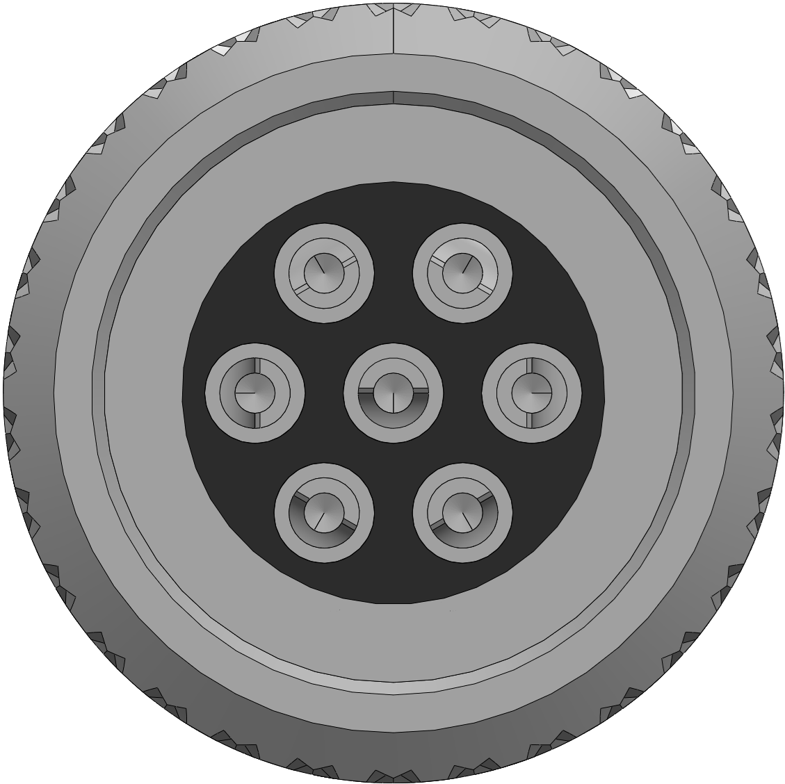
The GX12 7 pin female connector is a circular electrical connector designed for secure and reliable connections in various applications. It features seven pins, making it suitable for transmitting multiple signals or power lines in a compact form factor. Its robust design ensures durability and resistance to environmental factors, making it ideal for industrial, automotive, and DIY electronics projects.
Explore Projects Built with gx12 - 7 pin female connector


Explore Projects Built with gx12 - 7 pin female connector
Common Applications and Use Cases
- Industrial equipment and machinery
- Robotics and automation systems
- Audio and video equipment
- DIY electronics and prototyping
- Power and signal transmission in harsh environments
Technical Specifications
The GX12 7 pin female connector is designed to meet the needs of a wide range of applications. Below are its key technical details:
General Specifications
| Parameter | Value |
|---|---|
| Connector Type | Circular |
| Number of Pins | 7 |
| Rated Voltage | 125V AC/DC |
| Rated Current | 5A |
| Contact Resistance | ≤ 5 mΩ |
| Insulation Resistance | ≥ 1000 MΩ |
| Operating Temperature | -40°C to +85°C |
| Material (Shell) | Zinc alloy with nickel plating |
| Material (Contacts) | Brass with silver plating |
Pin Configuration and Descriptions
The GX12 7 pin female connector has seven pins arranged in a circular pattern. Below is the pinout description:
| Pin Number | Description |
|---|---|
| 1 | Signal/Power Line 1 |
| 2 | Signal/Power Line 2 |
| 3 | Signal/Power Line 3 |
| 4 | Signal/Power Line 4 |
| 5 | Signal/Power Line 5 |
| 6 | Signal/Power Line 6 |
| 7 | Signal/Power Line 7 |
Note: The specific function of each pin depends on the application and wiring configuration.
Usage Instructions
How to Use the GX12 7 Pin Female Connector in a Circuit
Prepare the Wires:
- Strip the insulation from the wires you intend to connect.
- Ensure the wire gauge matches the connector's specifications (typically 20-24 AWG).
Solder the Wires:
- Unscrew the connector's back shell to access the solder cups.
- Solder each wire to the corresponding pin based on your circuit design.
- Use heat shrink tubing or insulation tape to prevent short circuits.
Assemble the Connector:
- After soldering, reassemble the back shell to secure the wires.
- Ensure the connector is tightly screwed to maintain a secure connection.
Connect to the Male Counterpart:
- Align the keying notch on the female connector with the male connector.
- Push the connectors together and screw the locking ring to secure the connection.
Important Considerations and Best Practices
- Polarity and Pin Mapping: Double-check the pin mapping to avoid incorrect connections.
- Soldering Precautions: Use a soldering iron with a fine tip and avoid overheating the pins.
- Environmental Protection: If used in harsh environments, consider using a waterproof version or additional sealing.
- Current and Voltage Ratings: Do not exceed the rated voltage (125V) or current (5A) to prevent damage.
Example: Connecting to an Arduino UNO
The GX12 7 pin female connector can be used to interface multiple signals with an Arduino UNO. Below is an example of how to connect it:
Circuit Diagram
- Pin 1: Connect to Arduino digital pin 2
- Pin 2: Connect to Arduino digital pin 3
- Pin 3: Connect to Arduino digital pin 4
- Pin 4: Connect to Arduino GND
- Pin 5: Connect to Arduino 5V
- Pin 6: Reserved for additional signal
- Pin 7: Reserved for additional signal
Arduino Code Example
// Example code for reading signals from a GX12 7 pin female connector
// connected to an Arduino UNO

// Define pin connections
const int pin1 = 2; // Signal from GX12 pin 1
const int pin2 = 3; // Signal from GX12 pin 2
const int pin3 = 4; // Signal from GX12 pin 3

void setup() {
  // Initialize serial communication
  Serial.begin(9600);

  // Set pins as input
  pinMode(pin1, INPUT);
  pinMode(pin2, INPUT);
  pinMode(pin3, INPUT);
}

void loop() {
  // Read signals from the GX12 connector
  int signal1 = digitalRead(pin1);
  int signal2 = digitalRead(pin2);
  int signal3 = digitalRead(pin3);

  // Print the signals to the Serial Monitor
  Serial.print("Signal 1: ");
  Serial.println(signal1);
  Serial.print("Signal 2: ");
  Serial.println(signal2);
  Serial.print("Signal 3: ");
  Serial.println(signal3);

  // Add a small delay
  delay(500);
}
Troubleshooting and FAQs
Common Issues and Solutions
Loose Connection:
- Ensure the connector is properly screwed into the male counterpart.
- Check for damaged threads or misalignment.
Signal Interference:
- Use shielded cables to reduce noise in high-frequency applications.
- Ensure proper grounding of the circuit.
Overheating:
- Verify that the current and voltage do not exceed the rated limits.
- Inspect for poor solder joints that may cause resistance and heat buildup.
Pin Misalignment:
- Double-check the pin mapping and wiring before soldering.
- Use a multimeter to verify continuity.
FAQs
Q: Can the GX12 7 pin female connector be used outdoors?
A: Yes, but it is recommended to use a waterproof version or additional sealing to protect against moisture.
Q: What tools are needed to solder the connector?
A: You will need a soldering iron, solder wire, heat shrink tubing, and wire strippers.
Q: Can this connector handle high-frequency signals?
A: While it can handle moderate frequencies, shielded cables are recommended for high-frequency applications to minimize interference.
Q: Is the connector compatible with other GX series connectors?
A: The GX12 7 pin female connector is compatible with the GX12 7 pin male connector. Ensure the pin count and size match when selecting counterparts.