
How to Use RP LiDAR C1: Examples, Pinouts, and Specs
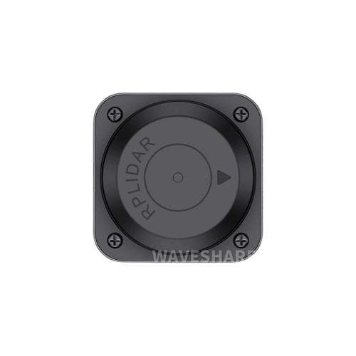
 Design with RP LiDAR C1 in Cirkit Designer
Introduction
The RP LiDAR C1, manufactured by SLAMTEC, is a compact and high-performance LiDAR sensor designed for precise distance measurement and 3D mapping. Utilizing advanced laser technology, it scans the surrounding environment to provide real-time data, making it an essential component for applications in robotics, autonomous vehicles, and geographic information systems (GIS). Its small form factor and robust performance make it ideal for both hobbyist projects and industrial applications.
Explore Projects Built with RP LiDAR C1
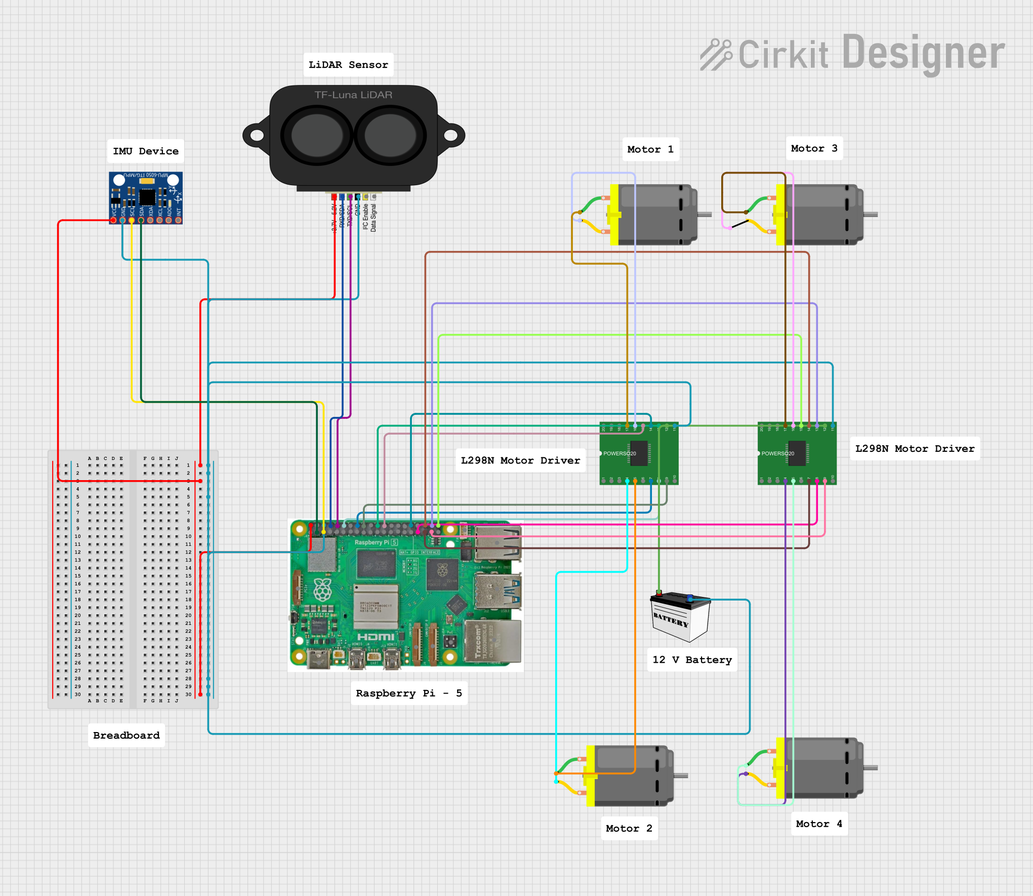 Open Project in Cirkit Designer
 Open Project in Cirkit Designer
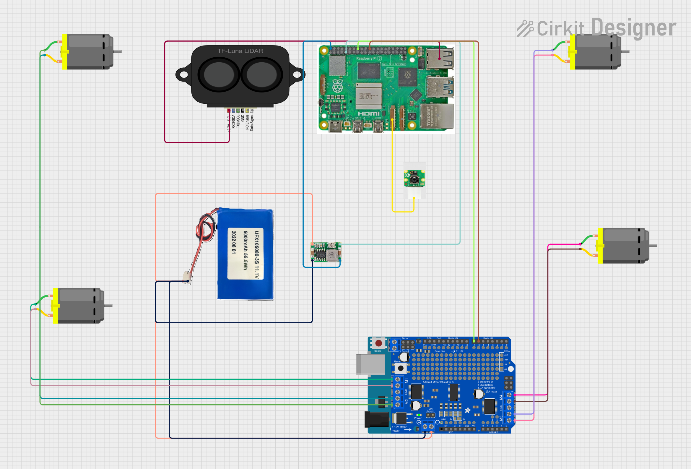 Open Project in Cirkit Designer
 Open Project in Cirkit Designer
Explore Projects Built with RP LiDAR C1
Open Project in Cirkit DesignerOpen Project in Cirkit DesignerOpen Project in Cirkit DesignerOpen Project in Cirkit DesignerCommon Applications
- Autonomous navigation for robots and drones
- Obstacle detection and avoidance
- 3D mapping and modeling
- Geographic information systems (GIS)
- Smart home and security systems
Technical Specifications
The RP LiDAR C1 is engineered to deliver reliable performance in a variety of environments. Below are its key technical details:
General Specifications
| Parameter | Value |
|---|---|
| Measurement Range | 0.15 m to 12 m |
| Scanning Frequency | 6 Hz to 12 Hz (adjustable) |
| Angular Resolution | 1° to 2° |
| Distance Resolution | < 1% of the measured distance |
| Operating Voltage | 5 V DC |
| Power Consumption | < 2.5 W |
| Communication Interface | UART (3.3V TTL) |
| Dimensions | 70 mm × 70 mm × 41 mm |
| Weight | 190 g |
Pin Configuration
The RP LiDAR C1 features a simple pinout for easy integration into your projects. Below is the pin configuration:
| Pin Number | Pin Name | Description |
|---|---|---|
| 1 | VCC | Power supply input (5 V DC) |
| 2 | GND | Ground |
| 3 | TX | UART Transmit (3.3V TTL) |
| 4 | RX | UART Receive (3.3V TTL) |
| 5 | PWM | Motor speed control (optional, 3.3V logic) |
Usage Instructions
The RP LiDAR C1 is straightforward to use in a variety of applications. Below are the steps and best practices for integrating it into your project.
Connecting the RP LiDAR C1
- Power Supply: Connect the VCC pin to a stable 5 V DC power source and the GND pin to ground.
- Data Communication: Use the TX and RX pins to establish a UART connection with your microcontroller or computer. Ensure the UART logic level is 3.3V to avoid damaging the LiDAR.
- Motor Control (Optional): If you need to control the motor speed, connect the PWM pin to a 3.3V PWM signal from your microcontroller.
Using with Arduino UNO
To use the RP LiDAR C1 with an Arduino UNO, follow these steps:
- Connect the VCC and GND pins to the Arduino's 5V and GND pins, respectively.
- Use a logic level shifter to connect the TX and RX pins to the Arduino's digital pins (e.g., TX to D10, RX to D11).
- Install the SLAMTEC RPLIDAR library in the Arduino IDE.
- Use the following example code to read data from the LiDAR:
#include <RPLidar.h>

// Define pins for LiDAR connection
#define RPLIDAR_RX 10  // RX pin connected to Arduino D10
#define RPLIDAR_TX 11  // TX pin connected to Arduino D11

RPLidar lidar;  // Create an RPLidar object

void setup() {
  Serial.begin(115200);  // Initialize serial communication for debugging
  lidar.begin(&Serial1); // Initialize LiDAR communication on Serial1
}

void loop() {
  if (IS_OK(lidar.waitPoint())) {
    // Wait for a valid measurement point
    float distance = lidar.getCurrentPoint().distance; // Get distance in mm
    float angle = lidar.getCurrentPoint().angle;       // Get angle in degrees
    bool isValid = lidar.getCurrentPoint().quality > 0; // Check if data is valid

    if (isValid) {
      Serial.print("Distance: ");
      Serial.print(distance / 1000.0); // Convert mm to meters
      Serial.print(" m, Angle: ");
      Serial.print(angle);
      Serial.println("°");
    }
  } else {
    Serial.println("Error reading LiDAR data.");
  }
}
Best Practices
- Ensure the LiDAR is mounted securely to avoid vibrations that could affect measurements.
- Avoid exposing the sensor to direct sunlight or reflective surfaces, as these can interfere with laser readings.
- Use a stable power supply to prevent voltage fluctuations that may disrupt operation.
- Regularly clean the LiDAR's lens to maintain accuracy.
Troubleshooting and FAQs
Common Issues and Solutions
No Data Output
- Cause: Incorrect wiring or UART configuration.
- Solution: Double-check the connections and ensure the UART baud rate matches the LiDAR's default (115200 bps).
Inaccurate Measurements
- Cause: Dirty lens or reflective surfaces in the environment.
- Solution: Clean the lens with a soft, lint-free cloth and avoid placing the LiDAR near reflective objects.
Motor Not Spinning
- Cause: PWM pin not connected or incorrect signal.
- Solution: Verify the PWM connection and ensure the signal is within the 3.3V logic level.
Interference with Other Sensors
- Cause: Overlapping laser signals from multiple LiDARs.
- Solution: Space out the LiDARs and adjust their scanning frequencies if possible.
FAQs
Q: Can the RP LiDAR C1 operate outdoors?
A: Yes, but it is recommended to avoid direct sunlight and extreme weather conditions for optimal performance.
Q: What is the maximum range of the RP LiDAR C1?
A: The maximum range is 12 meters under ideal conditions.
Q: Can I use the RP LiDAR C1 with a Raspberry Pi?
A: Yes, the RP LiDAR C1 can be connected to a Raspberry Pi via its UART interface. Use the appropriate libraries for data processing.
Q: How do I adjust the scanning frequency?
A: The scanning frequency can be adjusted via software commands sent through the UART interface.
By following this documentation, you can effectively integrate and utilize the RP LiDAR C1 in your projects. For further assistance, refer to the official SLAMTEC user manual.