Cirkit Designer Logo
Cirkit Designer
Your all-in-one circuit design IDE
Home / 
Component Documentation

How to Use ESP32-32E: Examples, Pinouts, and Specs

Image of ESP32-32E
Cirkit Designer LogoDesign with ESP32-32E in Cirkit Designer

Introduction

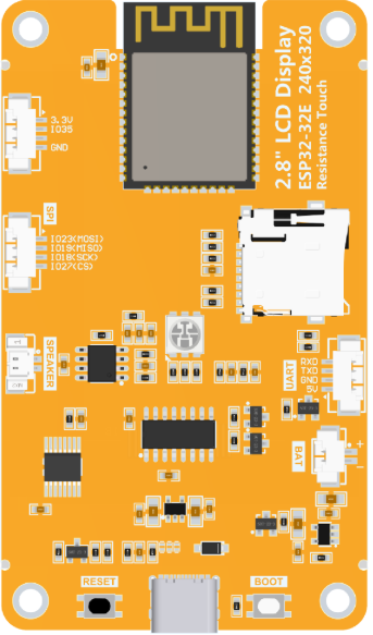
The ESP32-32E is a powerful microcontroller with integrated Wi-Fi and Bluetooth capabilities, designed for Internet of Things (IoT) applications. It features dual-core processing, a variety of GPIO pins, and supports multiple communication protocols, making it an excellent choice for smart devices, home automation, and industrial control systems.

Explore Projects Built with ESP32-32E

Use Cirkit Designer to design, explore, and prototype these projects online. Some projects support real-time simulation. Click "Open Project" to start designing instantly!
ESP32-Based Sensor Monitoring System with OLED Display and E-Stop
Image of MVP_design: A project utilizing ESP32-32E in a practical application
This circuit features an ESP32 microcontroller that interfaces with a variety of sensors and output devices. It is powered by a Lipo battery through a buck converter, ensuring a stable voltage supply. The ESP32 collects data from a DHT11 temperature and humidity sensor and a vibration sensor, controls a buzzer, and displays information on an OLED screen. An emergency stop (E Stop) is connected for safety purposes, allowing the system to be quickly deactivated.
Cirkit Designer LogoOpen Project in Cirkit Designer
ESP32-Based Smart Agriculture System with LoRa Communication
Image of Soil Monitoring Device: A project utilizing ESP32-32E in a practical application
This circuit features an ESP32 Devkit V1 microcontroller as the central processing unit, interfacing with various sensors including a PH Meter, an NPK Soil Sensor, and a Soil Moisture Sensor for environmental data collection. It also includes an EBYTE LoRa E220 module for wireless communication. Power management is handled by a Step Up Boost Power Converter, which is connected to a 12V Battery, stepping up the voltage to power the ESP32 and sensors, with common ground connections throughout the circuit.
Cirkit Designer LogoOpen Project in Cirkit Designer
ESP32-Based RF Communication System with 433 MHz Modules
Image of 433 mhz: A project utilizing ESP32-32E in a practical application
This circuit comprises an ESP32 microcontroller connected to a 433 MHz RF transmitter and receiver pair. The ESP32 is programmed to receive and decode RF signals through the receiver module, as well as send RF signals via the transmitter module. Additionally, the ESP32 can communicate with a Bluetooth device to exchange commands and data, and it uses an LED for status indication.
Cirkit Designer LogoOpen Project in Cirkit Designer
ESP32-Based Environmental Monitoring and Alert System with Solar Charging
Image of mark: A project utilizing ESP32-32E in a practical application
This circuit features an ESP32 Devkit V1 microcontroller connected to various sensors and modules for monitoring and communication purposes. It includes an MQ-2 gas sensor and a DHT11 temperature and humidity sensor, both interfaced with the ESP32 for environmental data collection. The circuit is powered by a 12V battery, regulated to 5V by step-down converters, and includes a solar charge controller connected to a solar panel for battery charging, a UPS module for power management, and a SIM900A module for GSM communication. Additionally, there is a WS2812 RGB LED strip for visual feedback and a piezo buzzer for audio alerts, both controlled by the ESP32.
Cirkit Designer LogoOpen Project in Cirkit Designer

Explore Projects Built with ESP32-32E

Use Cirkit Designer to design, explore, and prototype these projects online. Some projects support real-time simulation. Click "Open Project" to start designing instantly!
Image of MVP_design: A project utilizing ESP32-32E in a practical application
ESP32-Based Sensor Monitoring System with OLED Display and E-Stop
This circuit features an ESP32 microcontroller that interfaces with a variety of sensors and output devices. It is powered by a Lipo battery through a buck converter, ensuring a stable voltage supply. The ESP32 collects data from a DHT11 temperature and humidity sensor and a vibration sensor, controls a buzzer, and displays information on an OLED screen. An emergency stop (E Stop) is connected for safety purposes, allowing the system to be quickly deactivated.
Cirkit Designer LogoOpen Project in Cirkit Designer
Image of Soil Monitoring Device: A project utilizing ESP32-32E in a practical application
ESP32-Based Smart Agriculture System with LoRa Communication
This circuit features an ESP32 Devkit V1 microcontroller as the central processing unit, interfacing with various sensors including a PH Meter, an NPK Soil Sensor, and a Soil Moisture Sensor for environmental data collection. It also includes an EBYTE LoRa E220 module for wireless communication. Power management is handled by a Step Up Boost Power Converter, which is connected to a 12V Battery, stepping up the voltage to power the ESP32 and sensors, with common ground connections throughout the circuit.
Cirkit Designer LogoOpen Project in Cirkit Designer
Image of 433 mhz: A project utilizing ESP32-32E in a practical application
ESP32-Based RF Communication System with 433 MHz Modules
This circuit comprises an ESP32 microcontroller connected to a 433 MHz RF transmitter and receiver pair. The ESP32 is programmed to receive and decode RF signals through the receiver module, as well as send RF signals via the transmitter module. Additionally, the ESP32 can communicate with a Bluetooth device to exchange commands and data, and it uses an LED for status indication.
Cirkit Designer LogoOpen Project in Cirkit Designer
Image of mark: A project utilizing ESP32-32E in a practical application
ESP32-Based Environmental Monitoring and Alert System with Solar Charging
This circuit features an ESP32 Devkit V1 microcontroller connected to various sensors and modules for monitoring and communication purposes. It includes an MQ-2 gas sensor and a DHT11 temperature and humidity sensor, both interfaced with the ESP32 for environmental data collection. The circuit is powered by a 12V battery, regulated to 5V by step-down converters, and includes a solar charge controller connected to a solar panel for battery charging, a UPS module for power management, and a SIM900A module for GSM communication. Additionally, there is a WS2812 RGB LED strip for visual feedback and a piezo buzzer for audio alerts, both controlled by the ESP32.
Cirkit Designer LogoOpen Project in Cirkit Designer

Common Applications and Use Cases

  • Smart home devices (e.g., smart lights, thermostats)
  • IoT sensors and data loggers
  • Wireless communication hubs
  • Robotics and automation systems
  • Wearable devices
  • Industrial monitoring and control

Technical Specifications

The ESP32-32E is a versatile microcontroller with the following key specifications:

Specification Details
Microcontroller Dual-core Xtensa® 32-bit LX6 processor
Clock Speed Up to 240 MHz
Flash Memory 4 MB (varies by model)
SRAM 520 KB
Wi-Fi 802.11 b/g/n, 2.4 GHz
Bluetooth Bluetooth 4.2 and BLE (Bluetooth Low Energy)
GPIO Pins 34 GPIO pins (multiplexed with other functions)
ADC Channels 18 channels, 12-bit resolution
DAC Channels 2 channels, 8-bit resolution
Communication Protocols UART, SPI, I2C, I2S, CAN, PWM
Operating Voltage 3.3V
Input Voltage Range 3.0V to 3.6V
Power Consumption Ultra-low power modes available
Operating Temperature -40°C to +85°C

Pin Configuration and Descriptions

The ESP32-32E has a variety of pins for different functionalities. Below is a summary of the pin configuration:

Pin Name Function Description
GPIO0 GPIO, Boot Mode Selection Used for boot mode selection during startup.
GPIO1 (TXD0) UART TX Default UART0 transmit pin.
GPIO3 (RXD0) UART RX Default UART0 receive pin.
GPIO12-15 GPIO, SPI Can be used for SPI communication or general-purpose I/O.
GPIO16-17 GPIO, UART Can be used for UART communication or general-purpose I/O.
GPIO25-26 DAC Digital-to-Analog Converter pins.
GPIO32-39 ADC Analog-to-Digital Converter pins.
EN Enable Chip enable pin. Pull high to enable the chip.
3V3 Power Supply 3.3V power input.
GND Ground Ground connection.

Note: Some GPIO pins are multiplexed with other functions. Refer to the ESP32 datasheet for detailed pin assignments.

Usage Instructions

How to Use the ESP32-32E in a Circuit

  1. Power Supply: Provide a stable 3.3V power supply to the 3V3 pin. Ensure the current rating of the power source meets the ESP32-32E's requirements.
  2. Boot Mode: Connect GPIO0 to GND during startup to enter bootloader mode for programming. For normal operation, leave GPIO0 unconnected or pull it high.
  3. Programming: Use a USB-to-Serial adapter to connect the ESP32-32E to your computer. Connect the adapter's TX to RX (GPIO3) and RX to TX (GPIO1) on the ESP32-32E.
  4. Peripherals: Connect sensors, actuators, or other devices to the GPIO pins. Use appropriate pull-up or pull-down resistors if required.
  5. Wi-Fi and Bluetooth: Configure the Wi-Fi and Bluetooth settings in your code to enable wireless communication.

Important Considerations and Best Practices

  • Voltage Levels: The ESP32-32E operates at 3.3V logic levels. Avoid connecting 5V signals directly to its GPIO pins.
  • Power Supply: Use a decoupling capacitor (e.g., 10 µF) near the power pins to stabilize the power supply.
  • Heat Management: The ESP32-32E may generate heat during operation. Ensure proper ventilation or heat dissipation in your design.
  • Firmware Updates: Keep the ESP32 firmware updated to benefit from the latest features and bug fixes.

Example Code for Arduino UNO Integration

The ESP32-32E can be programmed using the Arduino IDE. Below is an example of how to connect the ESP32-32E to a Wi-Fi network:

#include <WiFi.h> // Include the Wi-Fi library for ESP32

// Replace with your network credentials
const char* ssid = "Your_SSID";
const char* password = "Your_PASSWORD";

void setup() {
  Serial.begin(115200); // Initialize serial communication at 115200 baud
  delay(1000); // Wait for a second to stabilize

  Serial.println("Connecting to Wi-Fi...");
  WiFi.begin(ssid, password); // Start Wi-Fi connection

  // Wait until the ESP32 is connected to the Wi-Fi network
  while (WiFi.status() != WL_CONNECTED) {
    delay(500);
    Serial.print(".");
  }

  Serial.println("\nWi-Fi connected!");
  Serial.print("IP Address: ");
  Serial.println(WiFi.localIP()); // Print the assigned IP address
}

void loop() {
  // Add your main code here
}

Note: Replace Your_SSID and Your_PASSWORD with your Wi-Fi network's credentials.

Troubleshooting and FAQs

Common Issues and Solutions

  1. ESP32-32E Not Connecting to Wi-Fi

    • Solution: Double-check the SSID and password in your code. Ensure the Wi-Fi network is within range and operational.
  2. GPIO Pins Not Responding

    • Solution: Verify that the pins are not being used for other functions (e.g., SPI, UART). Check for proper pull-up or pull-down resistors.
  3. Device Not Detected by Computer

    • Solution: Ensure the USB-to-Serial adapter is properly connected. Install the necessary drivers for the adapter.
  4. Overheating

    • Solution: Reduce the clock speed or optimize your code to minimize power consumption. Ensure proper ventilation.

FAQs

  • Q: Can the ESP32-32E operate on 5V?
    A: No, the ESP32-32E operates at 3.3V. Use a level shifter for 5V signals.

  • Q: How do I reset the ESP32-32E?
    A: Press the reset button (if available) or toggle the EN pin.

  • Q: Can I use the ESP32-32E with the Arduino IDE?
    A: Yes, the ESP32-32E is fully compatible with the Arduino IDE. Install the ESP32 board package to get started.

  • Q: What is the maximum range of the ESP32-32E's Wi-Fi?
    A: The range depends on environmental factors but typically extends up to 100 meters in open space.

This documentation provides a comprehensive guide to using the ESP32-32E effectively in your projects. For further details, refer to the official ESP32 datasheet and programming guides.