How to Use 5 direction button module: Examples, Pinouts, and Specs
Introduction
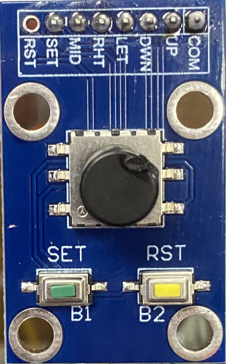
The 5 Direction Button Module is a compact input device featuring five tactile buttons arranged to provide directional input: up, down, left, right, and center (select). This module is widely used in user interfaces for navigation and control, making it ideal for projects involving menu systems, gaming controls, or robotic navigation. Its simple design and ease of integration make it a popular choice for hobbyists and professionals alike.
Common applications include:
- Menu navigation in embedded systems
- Game controllers
- Robotic control interfaces
- DIY projects requiring directional input
Explore Projects Built with 5 direction button module


Explore Projects Built with 5 direction button module
Technical Specifications
The 5 Direction Button Module is designed for low-power applications and is compatible with most microcontrollers, including Arduino boards. Below are the key technical details:
| Parameter | Value |
|---|---|
| Operating Voltage | 3.3V - 5V |
| Operating Current | < 10mA |
| Button Configuration | Up, Down, Left, Right, Center |
| Output Type | Digital (active low) |
| Dimensions | ~25mm x 25mm |
Pin Configuration
The module typically has 5 pins, which are described in the table below:
| Pin | Name | Description |
|---|---|---|
| 1 | UP | Outputs a LOW signal when the "Up" button is pressed |
| 2 | DOWN | Outputs a LOW signal when the "Down" button is pressed |
| 3 | LEFT | Outputs a LOW signal when the "Left" button is pressed |
| 4 | RIGHT | Outputs a LOW signal when the "Right" button is pressed |
| 5 | CENTER | Outputs a LOW signal when the "Center" (Select) button is pressed |
Usage Instructions
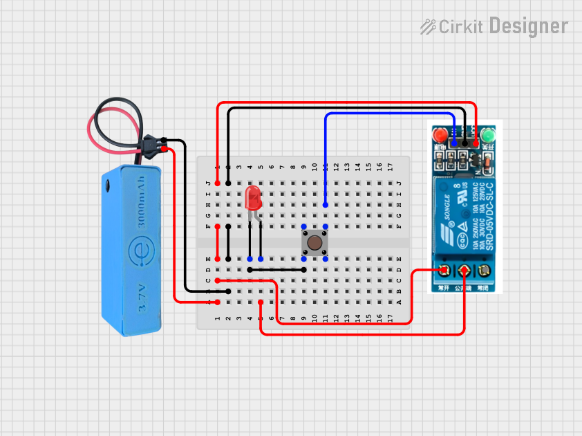
How to Use the Component in a Circuit
- Power the Module: Connect the module's VCC pin to a 3.3V or 5V power source and the GND pin to ground.
- Connect Output Pins: Connect the UP, DOWN, LEFT, RIGHT, and CENTER pins to the digital input pins of your microcontroller.
- Pull-Up Resistors: The module typically has built-in pull-up resistors, so the output pins remain HIGH when no button is pressed. When a button is pressed, the corresponding pin outputs a LOW signal.
- Read Button States: Use your microcontroller to monitor the state of each pin to detect button presses.
Important Considerations and Best Practices
- Debouncing: Mechanical buttons can produce noise or "bouncing" when pressed. Use software debouncing techniques to ensure reliable input detection.
- Voltage Compatibility: Ensure the module's operating voltage matches your microcontroller's input voltage levels.
- Pin Mapping: Double-check the pin connections to avoid incorrect readings or potential damage to the module.
Example Code for Arduino UNO
Below is an example Arduino sketch to read the button states and print them to the Serial Monitor:
// Pin definitions for the 5 Direction Button Module
const int upPin = 2;      // Connect UP pin to digital pin 2
const int downPin = 3;    // Connect DOWN pin to digital pin 3
const int leftPin = 4;    // Connect LEFT pin to digital pin 4
const int rightPin = 5;   // Connect RIGHT pin to digital pin 5
const int centerPin = 6;  // Connect CENTER pin to digital pin 6

void setup() {
  // Initialize serial communication
  Serial.begin(9600);

  // Set button pins as inputs with internal pull-up resistors
  pinMode(upPin, INPUT_PULLUP);
  pinMode(downPin, INPUT_PULLUP);
  pinMode(leftPin, INPUT_PULLUP);
  pinMode(rightPin, INPUT_PULLUP);
  pinMode(centerPin, INPUT_PULLUP);
}

void loop() {
  // Read the state of each button
  bool upState = digitalRead(upPin);
  bool downState = digitalRead(downPin);
  bool leftState = digitalRead(leftPin);
  bool rightState = digitalRead(rightPin);
  bool centerState = digitalRead(centerPin);

  // Print button states to the Serial Monitor
  Serial.print("UP: "); Serial.print(!upState); // LOW means pressed
  Serial.print(" | DOWN: "); Serial.print(!downState);
  Serial.print(" | LEFT: "); Serial.print(!leftState);
  Serial.print(" | RIGHT: "); Serial.print(!rightState);
  Serial.print(" | CENTER: "); Serial.println(!centerState);

  delay(100); // Small delay to reduce serial output flooding
}
Troubleshooting and FAQs
Common Issues and Solutions
No Response from Buttons:
- Cause: Incorrect wiring or loose connections.
- Solution: Double-check all connections and ensure the module is powered correctly.
Button Presses Not Detected:
- Cause: Missing pull-up resistors or incorrect pin configuration.
- Solution: Verify that the microcontroller pins are configured as
INPUT_PULLUP.
Multiple Buttons Trigger Simultaneously:
- Cause: Electrical noise or interference.
- Solution: Add capacitors (e.g., 0.1µF) across the button pins and ground to filter noise.
Debouncing Issues:
- Cause: Mechanical bouncing of the buttons.
- Solution: Implement software debouncing in your code (e.g., ignore rapid state changes).
FAQs
Q: Can I use this module with a 3.3V microcontroller like ESP32?
A: Yes, the module is compatible with both 3.3V and 5V systems.
Q: Do I need external pull-up resistors?
A: No, the module typically includes built-in pull-up resistors. However, verify this in your specific module's datasheet.
Q: How do I handle simultaneous button presses?
A: The module is designed for single-button detection. If multiple buttons are pressed, the behavior may vary depending on your circuit and code.
Q: Can I use this module for analog input?
A: No, this module provides digital outputs for each button. For analog input, consider using a joystick module instead.