How to Use Stepper Motor Driver: Examples, Pinouts, and Specs
Introduction
The COVVY TB6600 Stepper Motor Driver is a high-performance device designed to control the operation of stepper motors by sending precise electrical pulses. This allows for accurate positioning, speed control, and smooth operation of stepper motors in a variety of applications. The TB6600 is widely used in CNC machines, 3D printers, robotics, and other automation systems where precise motor control is essential.
Explore Projects Built with Stepper Motor Driver


Explore Projects Built with Stepper Motor Driver
Common Applications and Use Cases
- CNC machines for precise cutting, milling, and engraving
- 3D printers for accurate layer-by-layer printing
- Robotics for controlled movement and positioning
- Conveyor systems in industrial automation
- Camera sliders and other motion control systems
Technical Specifications
The TB6600 Stepper Motor Driver is designed to handle a wide range of stepper motors, offering flexibility and reliability in various applications.
Key Technical Details
| Parameter | Specification |
|---|---|
| Input Voltage Range | 9V to 42V DC |
| Output Current Range | 0.5A to 4.0A (adjustable) |
| Microstepping Modes | Full, 1/2, 1/4, 1/8, 1/16 |
| Control Signal Voltage | 3.3V to 5V (compatible with Arduino) |
| Step Frequency Range | 0 to 200 kHz |
| Operating Temperature | -10°C to +45°C |
| Dimensions | 96mm x 56mm x 33mm |
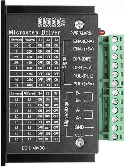
Pin Configuration and Descriptions
The TB6600 has a set of input and output terminals for connecting the stepper motor, power supply, and control signals.
Input Terminals
| Pin Name | Description |
|---|---|
| PUL+ | Positive terminal for the pulse signal (step signal) |
| PUL- | Negative terminal for the pulse signal |
| DIR+ | Positive terminal for the direction signal |
| DIR- | Negative terminal for the direction signal |
| ENA+ | Positive terminal for the enable signal (optional, used to enable/disable) |
| ENA- | Negative terminal for the enable signal |
Output Terminals
| Pin Name | Description |
|---|---|
| A+ | Positive terminal for one coil of the stepper motor |
| A- | Negative terminal for one coil of the stepper motor |
| B+ | Positive terminal for the other coil of the stepper motor |
| B- | Negative terminal for the other coil of the stepper motor |
Power Terminals
| Pin Name | Description |
|---|---|
| VCC | Positive terminal for the power supply (9V to 42V DC) |
| GND | Ground terminal for the power supply |
Usage Instructions
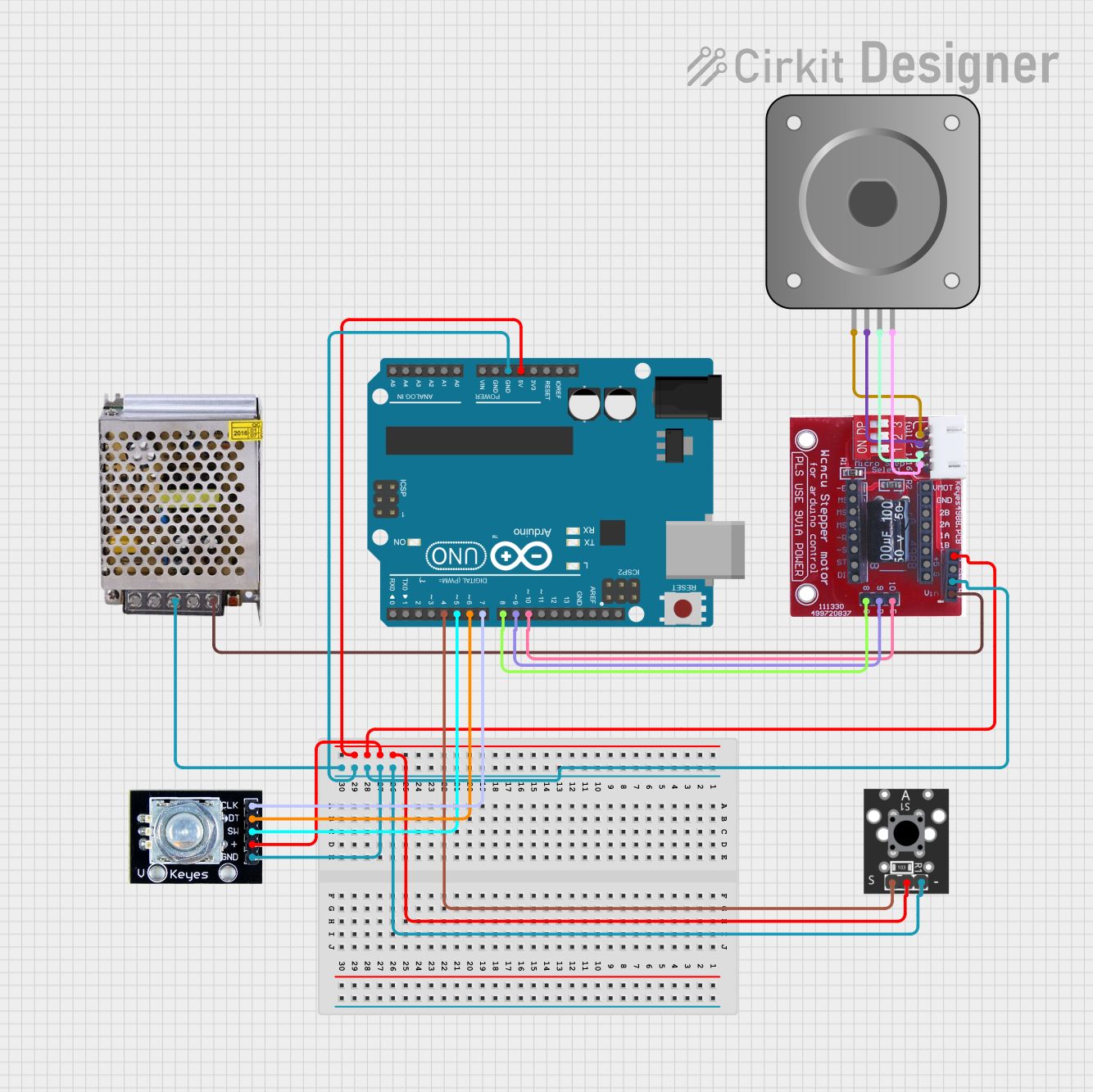
How to Use the TB6600 in a Circuit
- Connect the Stepper Motor:
- Attach the motor's coil wires to the A+/- and B+/- terminals of the TB6600. Ensure the connections match the motor's datasheet to avoid incorrect wiring.
- Power the Driver:
- Connect a DC power supply (9V to 42V) to the VCC and GND terminals. Ensure the power supply voltage matches the motor's requirements.
- Connect Control Signals:
- Use a microcontroller (e.g., Arduino UNO) to send pulse (PUL), direction (DIR), and enable (ENA) signals to the driver. Connect the PUL+, DIR+, and ENA+ pins to the microcontroller's digital output pins, and connect the PUL-, DIR-, and ENA- pins to the microcontroller's ground.
- Set the Current and Microstepping:
- Use the DIP switches on the TB6600 to configure the output current and microstepping mode. Refer to the TB6600 datasheet for the DIP switch settings.
- Test the Setup:
- Power on the system and send control signals from the microcontroller to test the motor's operation.
Important Considerations and Best Practices
- Current Settings: Ensure the current setting on the TB6600 matches the stepper motor's rated current to prevent overheating or damage.
- Cooling: The TB6600 has a built-in heatsink, but additional cooling (e.g., a fan) may be required for high-current applications.
- Signal Voltage: Ensure the control signal voltage (3.3V or 5V) is compatible with the microcontroller being used.
- Wiring: Double-check all connections before powering on the system to avoid short circuits or incorrect operation.
Example Code for Arduino UNO
Below is an example Arduino sketch to control a stepper motor using the TB6600:
// Define control pins for the TB6600
const int stepPin = 3;  // Pin connected to PUL+ on TB6600
const int dirPin = 4;   // Pin connected to DIR+ on TB6600
const int enablePin = 5; // Pin connected to ENA+ on TB6600

void setup() {
  // Set pin modes
  pinMode(stepPin, OUTPUT);
  pinMode(dirPin, OUTPUT);
  pinMode(enablePin, OUTPUT);

  // Enable the driver
  digitalWrite(enablePin, LOW); // LOW enables the driver
}

void loop() {
  // Set motor direction
  digitalWrite(dirPin, HIGH); // HIGH for one direction, LOW for the other

  // Generate step pulses
  for (int i = 0; i < 200; i++) { // 200 steps for one revolution (1.8°/step motor)
    digitalWrite(stepPin, HIGH);
    delayMicroseconds(500); // Adjust for speed (500 µs = 1 kHz step frequency)
    digitalWrite(stepPin, LOW);
    delayMicroseconds(500);
  }

  delay(1000); // Wait 1 second before reversing direction

  // Reverse direction
  digitalWrite(dirPin, LOW);
  for (int i = 0; i < 200; i++) {
    digitalWrite(stepPin, HIGH);
    delayMicroseconds(500);
    digitalWrite(stepPin, LOW);
    delayMicroseconds(500);
  }

  delay(1000); // Wait 1 second before repeating
}
Troubleshooting and FAQs
Common Issues and Solutions
Motor Not Moving:
- Check the wiring between the motor and the TB6600.
- Ensure the power supply voltage and current are sufficient for the motor.
- Verify the control signals from the microcontroller.
Motor Vibrates but Does Not Rotate:
- Check the motor coil connections (A+/A- and B+/B-). Incorrect wiring can cause this issue.
- Verify the microstepping settings on the DIP switches.
Driver Overheating:
- Ensure the current setting matches the motor's rated current.
- Add additional cooling, such as a fan, if necessary.
Inconsistent Motor Movement:
- Check the pulse signal frequency and ensure it is within the TB6600's supported range.
- Verify the microcontroller's timing and ensure no delays are causing missed steps.
FAQs
Q: Can the TB6600 drive a unipolar stepper motor?
A: No, the TB6600 is designed for bipolar stepper motors. Unipolar motors are not compatible.
Q: What is the maximum step frequency supported by the TB6600?
A: The TB6600 supports a maximum step frequency of 200 kHz.
Q: Can I use a 12V power supply with the TB6600?
A: Yes, the TB6600 supports input voltages from 9V to 42V, so a 12V power supply is compatible.
Q: How do I disable the driver?
A: Set the ENA+ pin to HIGH (or leave it unconnected) to disable the driver.