
How to Use iso 9141 click: Examples, Pinouts, and Specs
 Design with iso 9141 click in Cirkit Designer
Introduction
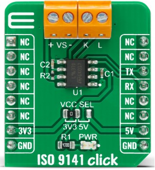
The ISO 9141 Click, manufactured by Meep, is a compact add-on board designed for seamless communication with automotive diagnostic systems using the ISO 9141 protocol. This protocol is widely used in On-Board Diagnostics (OBD) systems, enabling the retrieval of vehicle data for monitoring and troubleshooting purposes. The board simplifies interfacing with microcontrollers, making it an ideal choice for automotive diagnostics, data logging, and vehicle performance analysis.
Explore Projects Built with iso 9141 click
 Open Project in Cirkit Designer
 Open Project in Cirkit Designer
 Open Project in Cirkit Designer
 Open Project in Cirkit Designer
Explore Projects Built with iso 9141 click
Open Project in Cirkit DesignerOpen Project in Cirkit DesignerOpen Project in Cirkit DesignerOpen Project in Cirkit DesignerCommon Applications
- Reading and interpreting vehicle diagnostic data via OBD systems.
- Automotive performance monitoring and logging.
- Integration into microcontroller-based diagnostic tools.
- Educational and research projects in automotive electronics.
Technical Specifications
Key Technical Details
- Protocol Supported: ISO 9141
- Operating Voltage: 3.3V or 5V (selectable via onboard jumper)
- Communication Interface: UART
- Baud Rate: Configurable (typically 10.4 kbps for ISO 9141)
- Current Consumption: ~10 mA (idle), ~50 mA (active)
- Connector: Standard OBD-II interface
- Dimensions: 28.6mm x 25.4mm
Pin Configuration and Descriptions
The ISO 9141 Click uses a standard mikroBUS™ socket for easy integration. Below is the pinout:
| Pin | Label | Description |
|---|---|---|
| 1 | AN | Not connected (reserved for future use) |
| 2 | RST | Reset pin |
| 3 | CS | Not connected (reserved for future use) |
| 4 | SCK | Not connected (reserved for future use) |
| 5 | MISO | Not connected (reserved for future use) |
| 6 | MOSI | Not connected (reserved for future use) |
| 7 | PWM | Not connected (reserved for future use) |
| 8 | INT | Interrupt pin (optional use) |
| 9 | RX | UART Receive (connect to MCU TX) |
| 10 | TX | UART Transmit (connect to MCU RX) |
| 11 | SCL | Not connected (reserved for future use) |
| 12 | SDA | Not connected (reserved for future use) |
| 13 | 3.3V | Power supply (3.3V) |
| 14 | 5V | Power supply (5V) |
| 15 | GND | Ground |
Usage Instructions
How to Use the Component in a Circuit
- Power Supply: Connect the ISO 9141 Click to a 3.3V or 5V power source, depending on your microcontroller's logic level. Use the onboard jumper to select the appropriate voltage.
- UART Connection: Connect the RX pin of the Click board to the TX pin of your microcontroller, and the TX pin of the Click board to the RX pin of your microcontroller.
- OBD-II Connection: Plug the Click board into the vehicle's OBD-II port using the onboard connector.
- Initialization: Configure the UART communication on your microcontroller to match the ISO 9141 protocol's baud rate (typically 10.4 kbps).
- Data Retrieval: Send diagnostic commands via UART to retrieve vehicle data. The Click board will handle the ISO 9141 protocol communication.
Important Considerations and Best Practices
- Ensure the correct voltage level is selected using the onboard jumper to avoid damaging the board or your microcontroller.
- Use a stable power supply to prevent communication errors.
- Verify the baud rate and protocol settings on your microcontroller match the requirements of the ISO 9141 protocol.
- Avoid connecting the board to a vehicle while the engine is running to prevent electrical noise interference.
Example Code for Arduino UNO
Below is an example of how to use the ISO 9141 Click with an Arduino UNO to read vehicle data:
#include <SoftwareSerial.h>

// Define RX and TX pins for SoftwareSerial
#define RX_PIN 10  // Connect to ISO 9141 Click TX pin
#define TX_PIN 11  // Connect to ISO 9141 Click RX pin

// Initialize SoftwareSerial for communication with the Click board
SoftwareSerial iso9141Serial(RX_PIN, TX_PIN);

void setup() {
  // Start the hardware serial for debugging
  Serial.begin(9600);
  while (!Serial);

  // Start the SoftwareSerial for ISO 9141 communication
  iso9141Serial.begin(10400); // Baud rate for ISO 9141 protocol
  Serial.println("ISO 9141 Click Initialized");
}

void loop() {
  // Send a sample diagnostic command (e.g., request engine RPM)
  iso9141Serial.write("01 0C\r"); // Example OBD-II PID command for RPM
  delay(100); // Wait for a response

  // Check if data is available from the Click board
  if (iso9141Serial.available()) {
    Serial.println("Response from ISO 9141 Click:");
    while (iso9141Serial.available()) {
      char c = iso9141Serial.read();
      Serial.print(c); // Print the response to the Serial Monitor
    }
    Serial.println();
  }

  delay(1000); // Wait before sending the next command
}
Notes:
- Replace the sample command (
01 0C\r) with the appropriate OBD-II PID command for your application. - Ensure the Arduino UNO is powered via USB or an external power source when connected to the Click board.
Troubleshooting and FAQs
Common Issues and Solutions
No Response from the Click Board:
- Verify the RX and TX connections between the Click board and the microcontroller.
- Ensure the correct baud rate (10.4 kbps) is configured on the microcontroller.
- Check the power supply voltage and jumper settings.
Corrupted Data or Communication Errors:
- Use shorter cables to reduce signal degradation.
- Ensure the vehicle's OBD-II port is functioning correctly.
- Avoid running the vehicle's engine during data retrieval to minimize electrical noise.
Board Overheating:
- Check for proper voltage selection (3.3V or 5V).
- Ensure the board is not exposed to excessive ambient heat.
FAQs
Q: Can the ISO 9141 Click be used with other microcontrollers besides Arduino?
A: Yes, the Click board can be used with any microcontroller that supports UART communication, such as Raspberry Pi, STM32, or ESP32.
Q: What vehicles are compatible with the ISO 9141 Click?
A: The ISO 9141 protocol is commonly used in OBD-II systems for vehicles manufactured before 2008. Verify your vehicle's OBD-II protocol before use.
Q: How do I change the baud rate?
A: The baud rate is fixed at 10.4 kbps for ISO 9141 communication. Ensure your microcontroller is configured to match this rate.
Q: Can I use this board for real-time data logging?
A: Yes, the board supports real-time data retrieval, making it suitable for data logging applications. Ensure your microcontroller has sufficient processing power and storage for logging.