How to Use Adafruit PA1010D Mini GPS Module: Examples, Pinouts, and Specs
Introduction
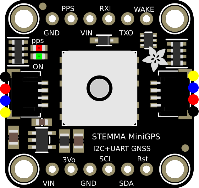
The Adafruit PA1010D Mini GPS Module is a compact and highly efficient GPS receiver designed to provide accurate location data. It supports multiple GPS protocols, making it versatile for a wide range of applications. With its small form factor and low power consumption, this module is ideal for portable and embedded systems, including drones, IoT devices, and navigation systems.
Explore Projects Built with Adafruit PA1010D Mini GPS Module
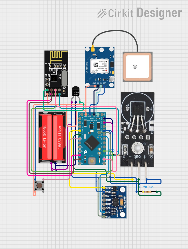
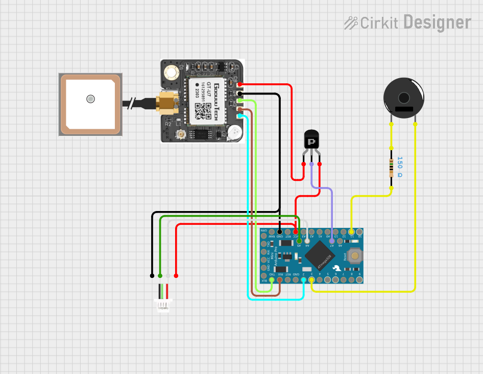

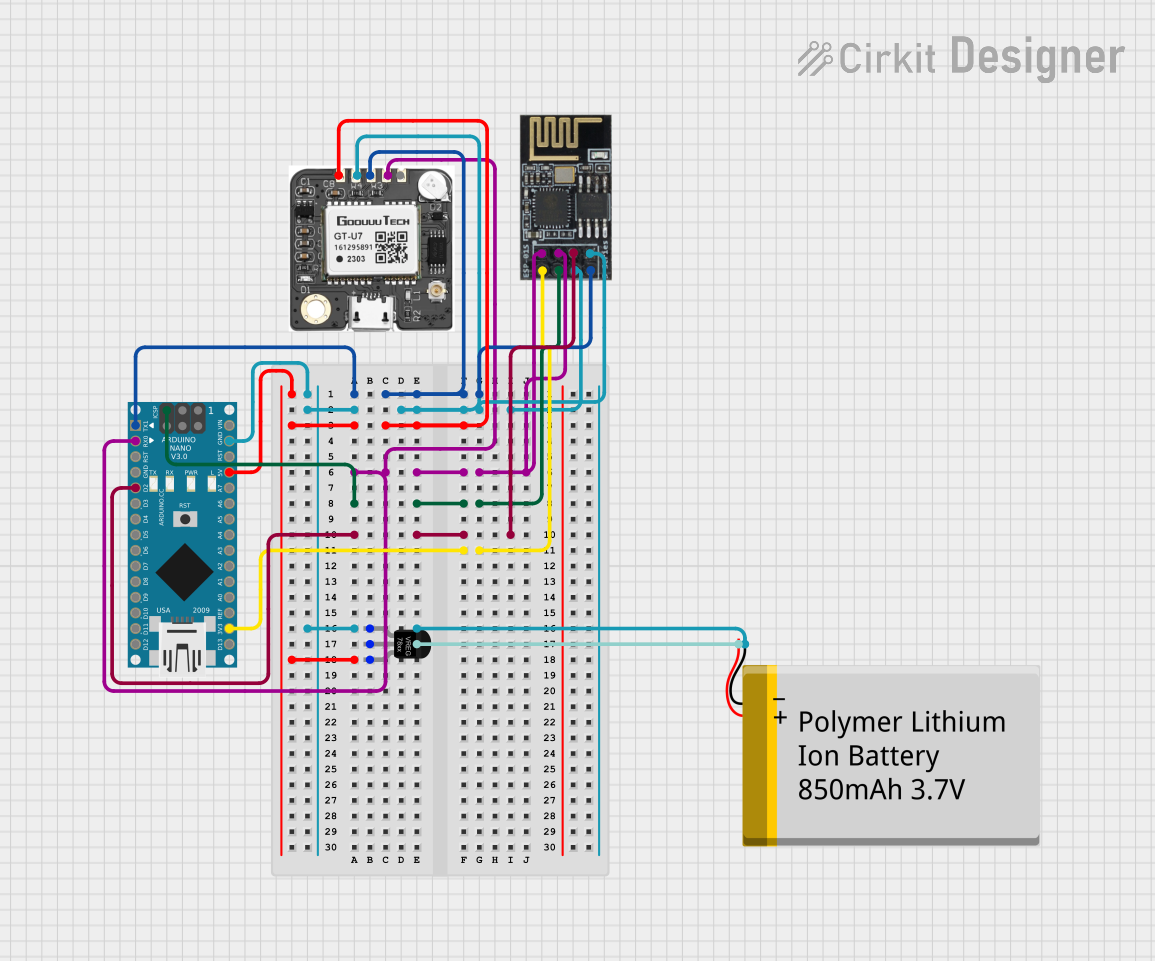
Explore Projects Built with Adafruit PA1010D Mini GPS Module
Common Applications and Use Cases
- GPS tracking for drones and robotics
- Navigation systems for vehicles
- IoT devices requiring geolocation
- Portable GPS-enabled devices
- Time synchronization for embedded systems
Technical Specifications
The Adafruit PA1010D Mini GPS Module is built for precision and reliability. Below are its key technical details:
Key Specifications
- Chipset: MTK3333
- Communication Protocols: I2C and UART
- Operating Voltage: 3.3V to 5V
- Current Consumption: ~20mA (typical)
- Position Accuracy: ±3 meters
- Update Rate: Up to 10 Hz
- Antenna: Built-in ceramic patch antenna
- Supported GPS Protocols: NMEA, PMTK
- Operating Temperature: -40°C to +85°C
- Dimensions: 16mm x 16mm x 6mm
Pin Configuration and Descriptions
The module has a total of 6 pins. Below is the pinout and description:
| Pin | Name | Description |
|---|---|---|
| 1 | VIN | Power input (3.3V to 5V). Supplies power to the module. |
| 2 | GND | Ground. Connect to the ground of your circuit. |
| 3 | SCL | I2C clock line. Used for communication with microcontrollers. |
| 4 | SDA | I2C data line. Used for communication with microcontrollers. |
| 5 | RX | UART receive pin. Used for serial communication (optional). |
| 6 | TX | UART transmit pin. Used for serial communication (optional). |
Usage Instructions
The Adafruit PA1010D Mini GPS Module can be easily integrated into your project using either I2C or UART communication. Below are the steps to use the module in a circuit:
Connecting the Module
- Power Supply: Connect the VIN pin to a 3.3V or 5V power source and the GND pin to the ground.
- I2C Communication:
- Connect the SCL pin to the I2C clock pin of your microcontroller (e.g., Arduino UNO's A5 pin).
- Connect the SDA pin to the I2C data pin of your microcontroller (e.g., Arduino UNO's A4 pin).
- Optional UART Communication:
- Connect the RX pin to the TX pin of your microcontroller.
- Connect the TX pin to the RX pin of your microcontroller.
Arduino UNO Example Code
Below is an example of how to use the Adafruit PA1010D Mini GPS Module with an Arduino UNO via I2C:
#include <Wire.h>
#include <Adafruit_GPS.h>

// Create an Adafruit_GPS object using I2C communication
Adafruit_GPS GPS(&Wire);

void setup() {
  Serial.begin(115200); // Initialize serial monitor for debugging
  Serial.println("Adafruit PA1010D Mini GPS Module Test");

  // Initialize GPS module
  if (!GPS.begin(0x10)) { // Default I2C address is 0x10
    Serial.println("Failed to initialize GPS module!");
    while (1);
  }
  Serial.println("GPS module initialized!");

  // Configure GPS update rate and output format
  GPS.sendCommand(PMTK_SET_NMEA_UPDATE_1HZ); // Set update rate to 1 Hz
  GPS.sendCommand(PMTK_SET_NMEA_OUTPUT_RMCGGA); // Output RMC and GGA sentences
}

void loop() {
  // Check for new GPS data
  if (GPS.newNMEAreceived()) {
    if (!GPS.parse(GPS.lastNMEA())) {
      // If parsing fails, skip to the next loop iteration
      return;
    }
  }

  // Print GPS data to the serial monitor
  Serial.print("Latitude: "); Serial.println(GPS.latitude);
  Serial.print("Longitude: "); Serial.println(GPS.longitude);
  Serial.print("Altitude: "); Serial.println(GPS.altitude);
  Serial.print("Speed: "); Serial.println(GPS.speed);
  Serial.println();
  delay(1000); // Wait 1 second before the next update
}
Important Considerations and Best Practices
- Ensure the module has a clear view of the sky for optimal GPS signal reception.
- Use decoupling capacitors near the power pins to reduce noise.
- Avoid placing the module near high-frequency components or metal surfaces that may interfere with the GPS signal.
- If using UART communication, ensure the baud rate matches the module's default setting (9600 bps).
Troubleshooting and FAQs
Common Issues and Solutions
No GPS Fix:
- Ensure the module has a clear view of the sky.
- Wait for a few minutes, as the first GPS fix may take longer.
- Check the power supply voltage and connections.
No Data Received:
- Verify the I2C or UART connections.
- Ensure the correct I2C address (0x10) is used in the code.
- Check the baud rate if using UART communication.
Inaccurate Location Data:
- Ensure the module is not indoors or obstructed by large objects.
- Allow the module to receive data from multiple satellites for better accuracy.
FAQs
Q: Can the module work indoors?
A: The module may work indoors near windows, but signal reception is significantly better outdoors.
Q: What is the default I2C address of the module?
A: The default I2C address is 0x10.
Q: How long does it take to get a GPS fix?
A: The time to first fix (TTFF) can range from a few seconds to several minutes, depending on signal conditions.
Q: Can I use this module with a 5V microcontroller?
A: Yes, the module supports both 3.3V and 5V logic levels.
By following this documentation, you can effectively integrate the Adafruit PA1010D Mini GPS Module into your projects and troubleshoot common issues.