How to Use 11 channel spectral sensor: Examples, Pinouts, and Specs
AS7341 11-Channel Spectral Sensor Documentation
1. Introduction
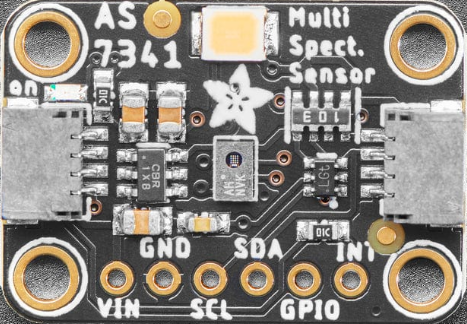
The AS7341 is an advanced 11-channel spectral sensor manufactured by OSRAM Group. This compact and highly versatile device is designed to detect and measure light intensity across 11 distinct wavelengths, ranging from ultraviolet (UV) to near-infrared (NIR). By analyzing spectral data, the AS7341 enables applications such as material identification, color analysis, and environmental monitoring.
Common Applications
- Color Analysis: Used in colorimeters for precise color matching and quality control.
- Material Identification: Identifies materials based on their optical properties.
- Ambient Light Sensing: Measures light intensity for smart lighting systems.
- Agriculture: Monitors plant health by analyzing reflected light.
- Wearable Devices: Integrated into health monitoring devices for skin tone analysis.
- Spectroscopy: Used in portable spectrometers for scientific research.
2. Technical Specifications
The AS7341 is a highly integrated spectral sensor with multiple features that make it suitable for a wide range of applications. Below are its key technical details and pin configuration.
Key Technical Details
| Parameter | Value |
|---|---|
| Manufacturer | OSRAM Group |
| Part Number | AS7341 |
| Spectral Channels | 11 (UV to NIR) |
| Spectral Range | 350 nm to 1000 nm |
| Communication Interface | I²C (Inter-Integrated Circuit) |
| Supply Voltage (VDD) | 1.8V to 3.6V |
| Operating Current | 190 µA (typical) |
| Power Modes | Low-power and high-resolution modes |
| Integration Time | Programmable (2.78 ms to 712 ms) |
| Package Type | 20-pin LGA (3.1 mm x 2.0 mm x 1.0 mm) |
| Operating Temperature | -40°C to +85°C |
Pin Configuration and Descriptions
| Pin Number | Pin Name | Description |
|---|---|---|
| 1 | VDD | Power supply input (1.8V to 3.6V). |
| 2 | GND | Ground connection. |
| 3 | SDA | I²C data line for communication. |
| 4 | SCL | I²C clock line for communication. |
| 5 | INT | Interrupt output pin (active low). |
| 6 | GPIO1 | General-purpose input/output pin. |
| 7 | GPIO2 | General-purpose input/output pin. |
| 8 | LED_CTRL | Controls an external LED for illumination. |
| 9-20 | NC | No connection (leave unconnected). |
3. Usage Instructions
Connecting the AS7341 to an Arduino UNO
The AS7341 communicates via the I²C protocol, making it easy to interface with microcontrollers like the Arduino UNO. Below is a step-by-step guide to connect and use the sensor:
Wiring Diagram
| AS7341 Pin | Arduino UNO Pin |
|---|---|
| VDD | 3.3V |
| GND | GND |
| SDA | A4 |
| SCL | A5 |
| INT | Digital Pin 2 |
Arduino Code Example
The following code demonstrates how to initialize the AS7341 and read spectral data using the Arduino IDE. This example uses the Adafruit AS7341 library, which simplifies communication with the sensor.
#include <Wire.h>
#include <Adafruit_AS7341.h>

// Create an instance of the AS7341 sensor
Adafruit_AS7341 as7341;

void setup() {
  Serial.begin(115200); // Initialize serial communication for debugging
  while (!Serial);

  // Initialize I²C communication
  if (!as7341.begin()) {
    Serial.println("AS7341 not detected. Check wiring!");
    while (1); // Halt execution if the sensor is not found
  }

  Serial.println("AS7341 initialized successfully!");

  // Configure the sensor for spectral measurement
  as7341.setATIME(100); // Set integration time (100 ms)
  as7341.setASTEP(999); // Set step size for integration
  as7341.setGain(AS7341_GAIN_16X); // Set gain to 16x
}

void loop() {
  // Read spectral data from all 11 channels
  uint16_t channelData[11];
  if (as7341.readAllChannels(channelData)) {
    Serial.println("Spectral Data:");
    for (int i = 0; i < 11; i++) {
      Serial.print("Channel ");
      Serial.print(i + 1);
      Serial.print(": ");
      Serial.println(channelData[i]);
    }
  } else {
    Serial.println("Failed to read spectral data.");
  }

  delay(1000); // Wait 1 second before the next reading
}
Important Considerations
- Power Supply: Ensure the sensor is powered with a stable voltage between 1.8V and 3.6V. Use a level shifter if interfacing with a 5V microcontroller.
- I²C Pull-Up Resistors: The I²C lines (SDA and SCL) require pull-up resistors (typically 4.7 kΩ) for proper operation.
- Interrupt Pin: The INT pin can be used to signal when new data is available, reducing the need for constant polling.
- Ambient Light: Avoid direct exposure to intense light sources, as this may saturate the sensor.
4. Troubleshooting and FAQs
Common Issues and Solutions
| Issue | Possible Cause | Solution |
|---|---|---|
| Sensor not detected by Arduino | Incorrect wiring or I²C address mismatch | Verify connections and ensure the correct I²C address is used (default: 0x39). |
| Spectral data is inconsistent | Ambient light interference | Shield the sensor from direct light sources or use a diffuser. |
| No data output | Integration time or gain not configured | Ensure proper configuration of integration time and gain settings. |
| I²C communication errors | Missing pull-up resistors on SDA/SCL lines | Add 4.7 kΩ pull-up resistors to the I²C lines. |
Frequently Asked Questions
What is the default I²C address of the AS7341?
- The default I²C address is 0x39.
Can the AS7341 measure light intensity in the infrared range?
- Yes, the AS7341 can measure light intensity in the near-infrared (NIR) range up to 1000 nm.
How do I improve measurement accuracy?
- Use proper calibration, shield the sensor from stray light, and ensure stable power supply.
Is the AS7341 compatible with 5V microcontrollers?
- Yes, but you must use a level shifter to step down the I²C signals to 3.3V.
5. Additional Resources
- Datasheet: AS7341 Datasheet
- Arduino Library: Adafruit AS7341 Library
- Application Notes: Refer to the manufacturer's application notes for advanced use cases.
This documentation provides a comprehensive guide to understanding, using, and troubleshooting the AS7341 spectral sensor. Whether you're a beginner or an experienced user, the AS7341 offers a powerful solution for spectral analysis in a compact package.
Explore Projects Built with 11 channel spectral sensor

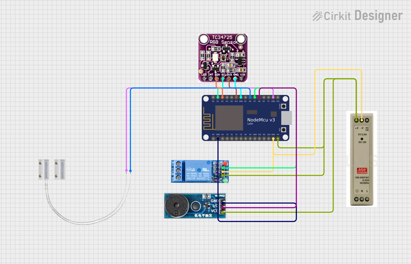
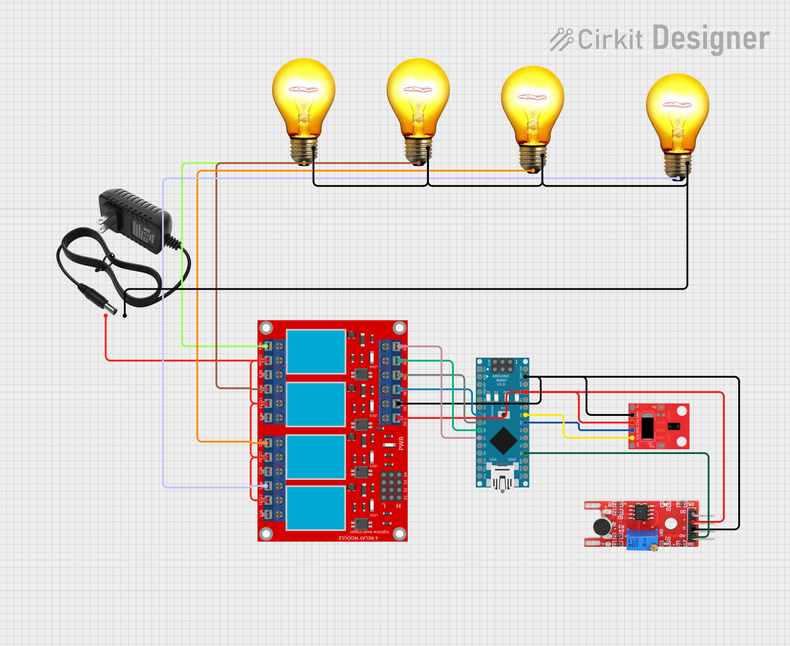
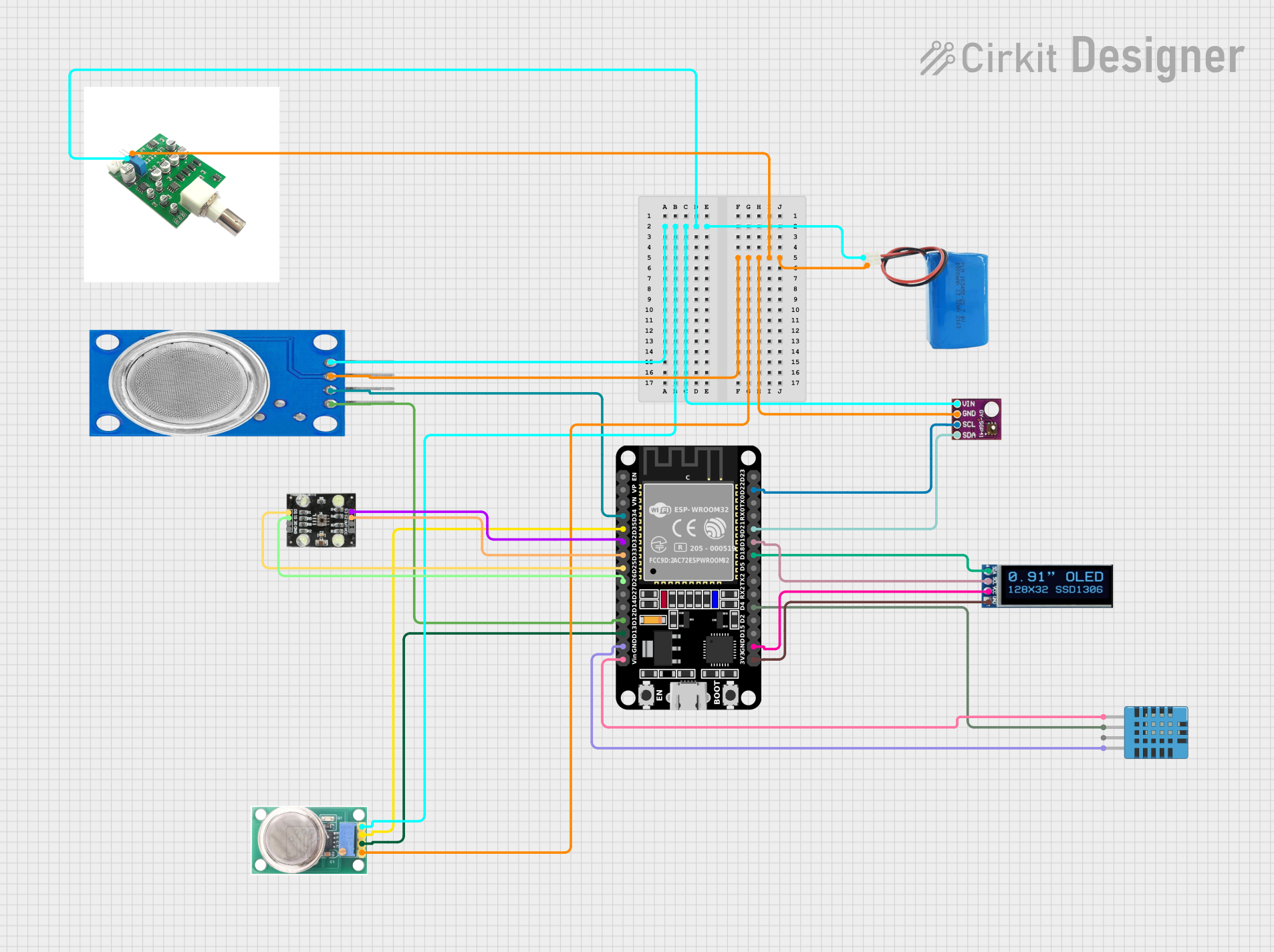
Explore Projects Built with 11 channel spectral sensor