
How to Use ESP 32U: Examples, Pinouts, and Specs

 Design with ESP 32U in Cirkit Designer
Introduction
The ESP 32U is a powerful microcontroller with integrated Wi-Fi and Bluetooth capabilities, designed specifically for Internet of Things (IoT) applications. It features a dual-core processor, ample GPIO pins, and supports various communication protocols, making it an excellent choice for smart devices, automation projects, and wireless communication systems.
Explore Projects Built with ESP 32U
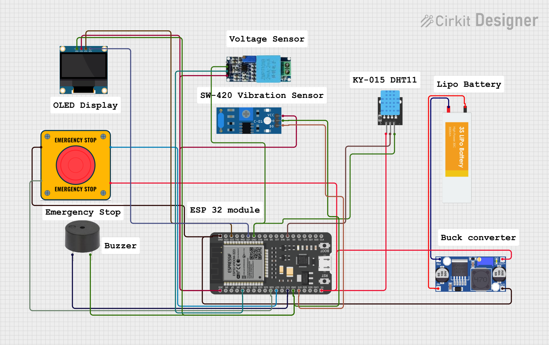 Open Project in Cirkit Designer
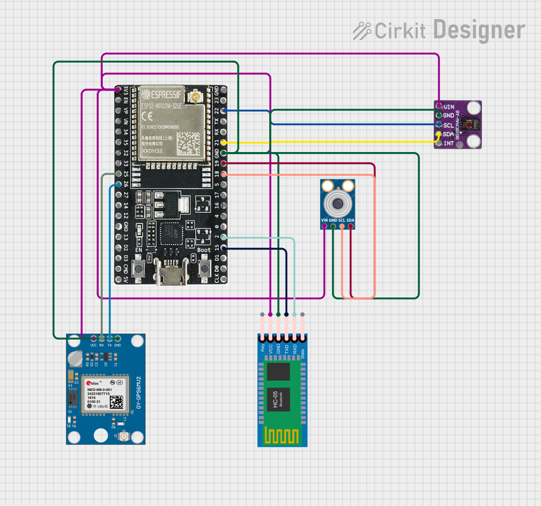 Open Project in Cirkit Designer
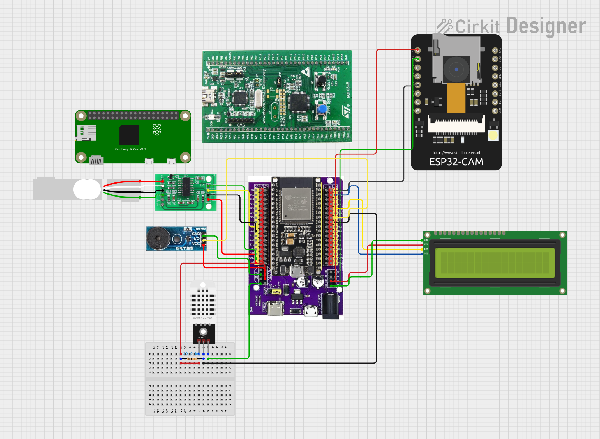 Open Project in Cirkit Designer
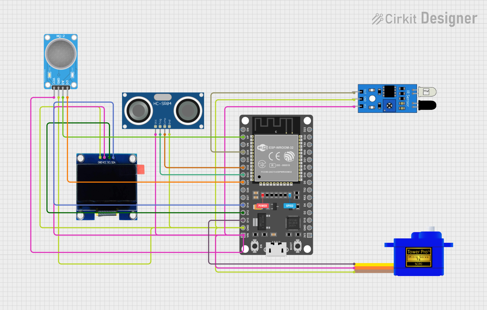 Open Project in Cirkit Designer
Explore Projects Built with ESP 32U
Open Project in Cirkit DesignerOpen Project in Cirkit DesignerOpen Project in Cirkit DesignerOpen Project in Cirkit DesignerCommon Applications and Use Cases
- Smart home devices (e.g., smart lights, thermostats)
- Industrial automation and monitoring
- Wearable technology
- Wireless sensor networks
- Robotics and drones
- IoT gateways and hubs
- Real-time data logging and remote control systems
Technical Specifications
Key Technical Details
| Parameter | Specification |
|---|---|
| Microcontroller | Xtensa® 32-bit LX6 dual-core processor |
| Clock Speed | Up to 240 MHz |
| Flash Memory | 4 MB (external) |
| SRAM | 520 KB |
| Wi-Fi | 802.11 b/g/n |
| Bluetooth | v4.2 BR/EDR and BLE |
| Operating Voltage | 3.3V |
| Input Voltage Range | 3.0V - 3.6V |
| GPIO Pins | 34 |
| Communication Protocols | UART, SPI, I2C, I2S, CAN, PWM |
| ADC Channels | 18 (12-bit resolution) |
| DAC Channels | 2 |
| Power Consumption | Ultra-low power (varies by mode) |
| Operating Temperature | -40°C to +85°C |
Pin Configuration and Descriptions
| Pin Number | Pin Name | Description |
|---|---|---|
| 1 | GND | Ground pin |
| 2 | 3V3 | 3.3V power supply input/output |
| 3 | EN | Enable pin (active high) |
| 4 | GPIO0 | General-purpose I/O, boot mode selection |
| 5-40 | GPIO1-GPIO34 | General-purpose I/O pins with multiple functions |
| 41 | ADC1/ADC2 | Analog-to-digital converter input pins |
| 42 | DAC1/DAC2 | Digital-to-analog converter output pins |
| 43 | TX/RX | UART communication pins |
| 44 | SPI/I2C | SPI and I2C communication pins |
Note: The exact pinout may vary depending on the ESP 32U module variant. Refer to the datasheet for detailed pin mappings.
Usage Instructions
How to Use the ESP 32U in a Circuit
- Power Supply: Provide a stable 3.3V power supply to the
3V3pin. Ensure the current rating of the power source meets the ESP 32U's requirements. - Boot Mode: Connect
GPIO0to GND during boot to enter programming mode. For normal operation, leave it unconnected or pull it high. - Communication: Use the UART pins (
TXandRX) for serial communication with a computer or other microcontrollers. Alternatively, use SPI or I2C for interfacing with sensors and peripherals. - GPIO Usage: Configure GPIO pins as input or output in your code. Be mindful of the voltage levels and current limits.
- Wi-Fi and Bluetooth: Use the built-in Wi-Fi and Bluetooth modules for wireless communication. Configure these features in your firmware.
Important Considerations and Best Practices
- Voltage Levels: The ESP 32U operates at 3.3V. Avoid applying 5V to any GPIO pin to prevent damage.
- Power Supply Stability: Use decoupling capacitors near the power pins to ensure stable operation.
- Heat Management: The ESP 32U can generate heat during operation. Ensure proper ventilation or heat dissipation in your design.
- Firmware Updates: Use the ESP-IDF or Arduino IDE to program and update the firmware. Always verify the firmware compatibility with the ESP 32U.
Example Code for Arduino UNO Integration
Below is an example of how to connect and program the ESP 32U using the Arduino IDE:
#include <WiFi.h> // Include the Wi-Fi library for ESP32

// Replace with your network credentials
const char* ssid = "Your_SSID";
const char* password = "Your_PASSWORD";

void setup() {
  Serial.begin(115200); // Initialize serial communication at 115200 baud
  delay(1000); // Wait for the serial monitor to initialize

  Serial.println("Connecting to Wi-Fi...");
  WiFi.begin(ssid, password); // Start Wi-Fi connection

  while (WiFi.status() != WL_CONNECTED) {
    delay(500); // Wait for connection
    Serial.print(".");
  }

  Serial.println("\nWi-Fi connected!");
  Serial.print("IP Address: ");
  Serial.println(WiFi.localIP()); // Print the device's IP address
}

void loop() {
  // Add your main code here
}
Note: Ensure the ESP 32U is connected to the Arduino UNO via UART (TX/RX) and powered correctly.
Troubleshooting and FAQs
Common Issues and Solutions
ESP 32U Not Responding
- Cause: Incorrect power supply or wiring.
- Solution: Verify the power supply voltage (3.3V) and check all connections.
Wi-Fi Connection Fails
- Cause: Incorrect SSID or password.
- Solution: Double-check the network credentials in your code.
Overheating
- Cause: Prolonged high-power operation or insufficient ventilation.
- Solution: Add a heat sink or improve airflow around the module.
GPIO Pins Not Working
- Cause: Incorrect pin configuration or exceeding current limits.
- Solution: Verify the pin mode in your code and ensure the current draw is within limits.
FAQs
Q: Can the ESP 32U operate at 5V?
A: No, the ESP 32U operates at 3.3V. Applying 5V to any pin may damage the module.
Q: How do I reset the ESP 32U?
A: Use the EN pin to reset the module. Pull it low momentarily and then release it.
Q: Can I use the ESP 32U with a 5V logic microcontroller?
A: Yes, but you must use a level shifter to convert 5V signals to 3.3V.
Q: What is the maximum range of the Wi-Fi module?
A: The range depends on environmental factors but typically extends up to 100 meters in open space.
Q: How do I update the firmware?
A: Use the ESP-IDF or Arduino IDE with a USB-to-serial adapter to upload new firmware. Ensure the module is in programming mode by grounding GPIO0 during boot.