How to Use IR-sensor HW-201: Examples, Pinouts, and Specs
Introduction
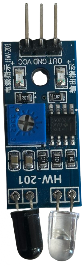
The IR-Sensor HW-201, manufactured by Cina, is an infrared sensor module designed for detecting obstacles and measuring distances. It operates by emitting infrared light and analyzing the reflected signal to determine the proximity of objects. This module is widely used in robotics, automation, and other applications requiring object detection or distance measurement. Its compact design and ease of integration make it a popular choice for hobbyists and professionals alike.
Explore Projects Built with IR-sensor HW-201

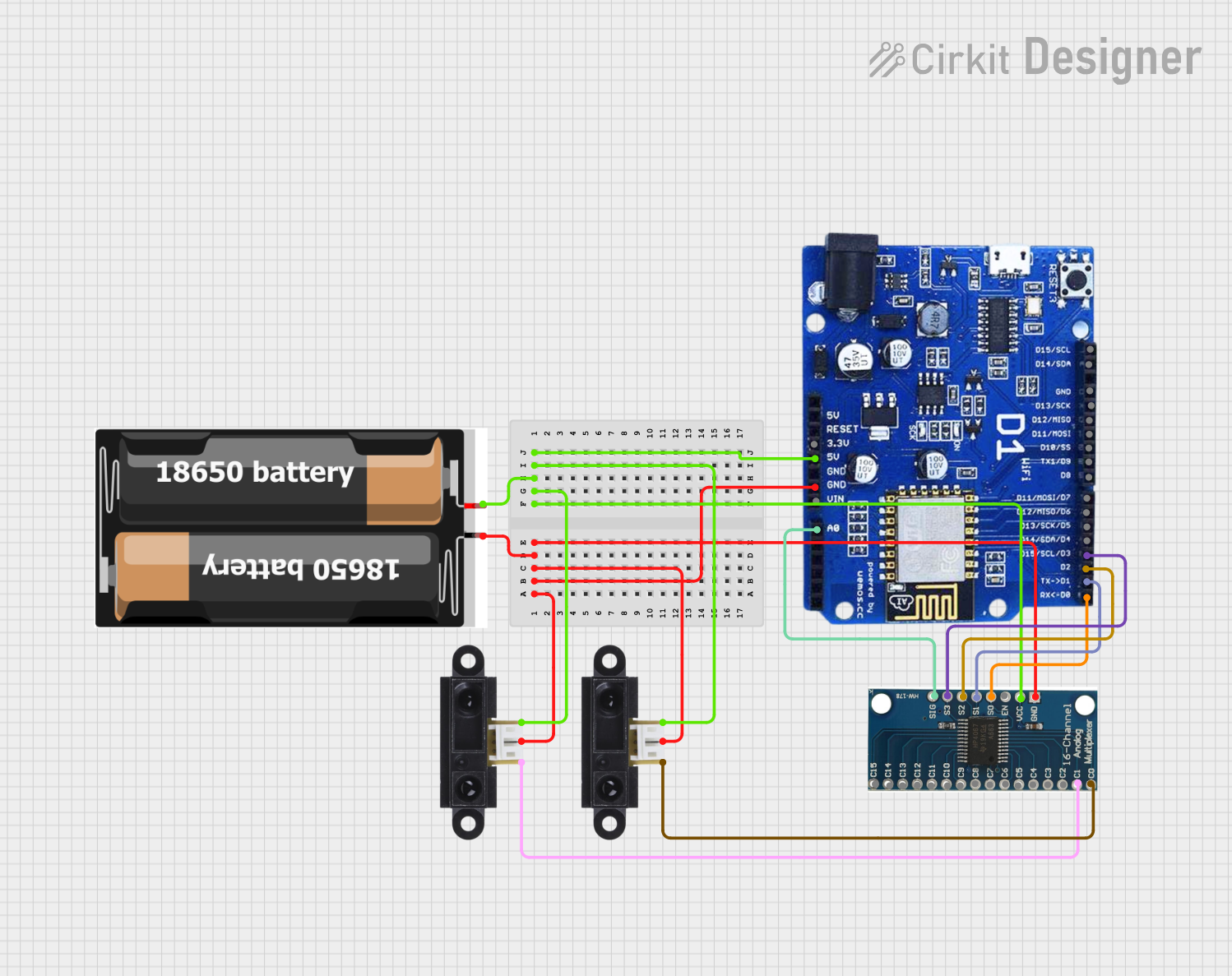
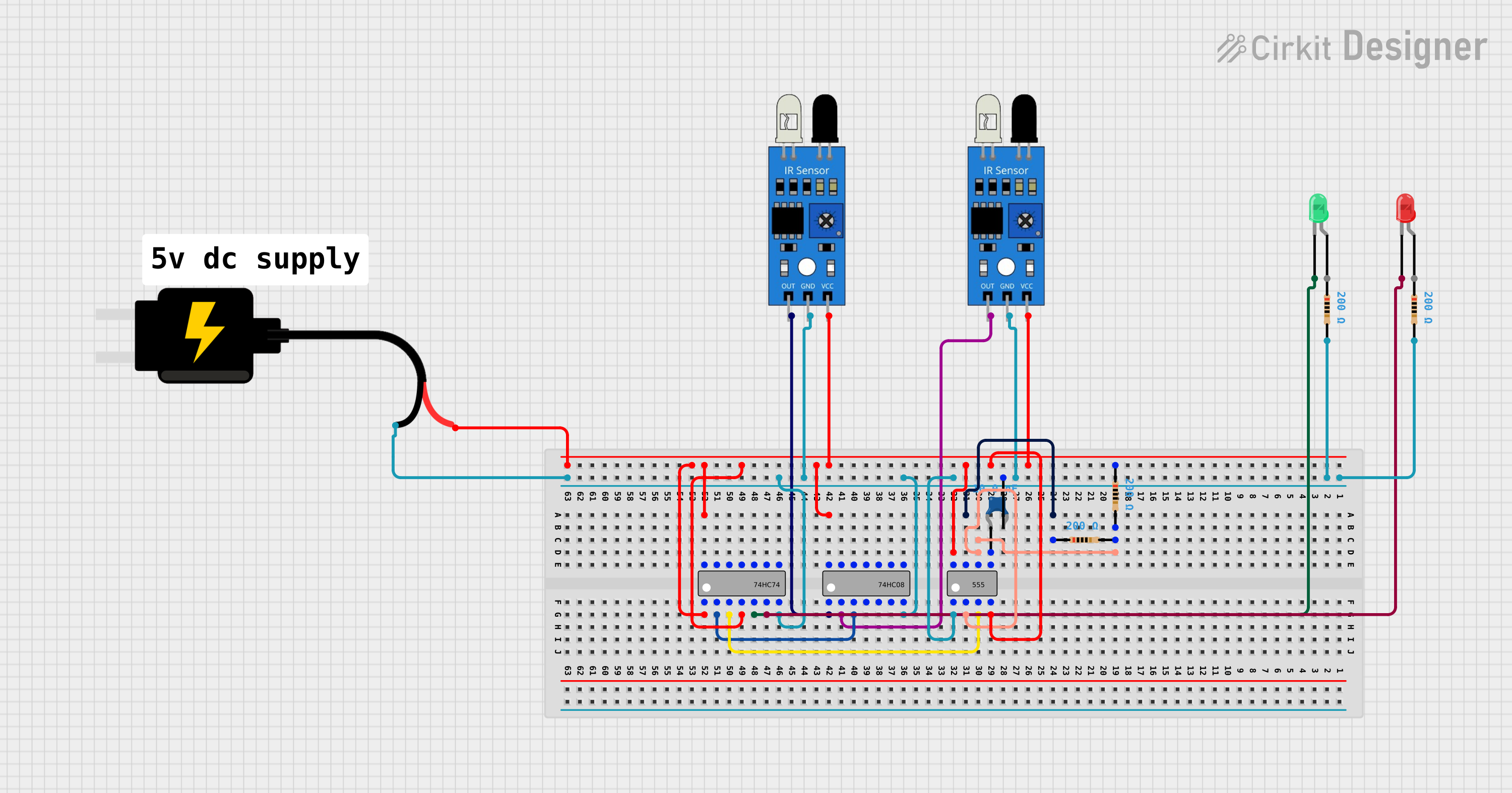

Explore Projects Built with IR-sensor HW-201
Common Applications
- Obstacle detection in robotics
- Line-following robots
- Proximity sensing in automation systems
- Object counting in conveyor systems
- Security systems for motion detection
Technical Specifications
Below are the key technical details of the IR-Sensor HW-201:
| Parameter | Value |
|---|---|
| Operating Voltage | 3.3V to 5V |
| Operating Current | 20mA (typical) |
| Detection Range | 2cm to 30cm |
| Output Type | Digital (High/Low) |
| Adjustable Sensitivity | Yes (via onboard potentiometer) |
| Dimensions | 32mm x 14mm x 8mm |
| Operating Temperature | -25°C to 85°C |
Pin Configuration and Descriptions
The HW-201 module has three pins for interfacing:
| Pin | Name | Description |
|---|---|---|
| 1 | VCC | Power supply pin. Connect to 3.3V or 5V. |
| 2 | GND | Ground pin. Connect to the ground of the circuit. |
| 3 | OUT | Digital output pin. Outputs HIGH (1) when no obstacle is detected, LOW (0) when an obstacle is detected. |
Usage Instructions
How to Use the IR-Sensor HW-201 in a Circuit
- Power the Module: Connect the
VCCpin to a 3.3V or 5V power source and theGNDpin to the ground. - Connect the Output: Connect the
OUTpin to a digital input pin of your microcontroller or directly to an external circuit. - Adjust Sensitivity: Use the onboard potentiometer to adjust the detection range. Turn clockwise to increase sensitivity and counterclockwise to decrease it.
- Test the Module: Place an object within the detection range and observe the
OUTpin. It will output LOW (0) when an obstacle is detected and HIGH (1) otherwise.
Important Considerations and Best Practices
- Power Supply: Ensure a stable power supply to avoid erratic behavior.
- Ambient Light: The sensor may be affected by strong ambient infrared light sources (e.g., sunlight). Use it in controlled lighting conditions for optimal performance.
- Mounting: Avoid placing reflective surfaces directly in front of the sensor, as this may cause false readings.
- Wiring: Keep the wiring short and secure to minimize noise and interference.
Example: Connecting to an Arduino UNO
Below is an example of how to connect and use the HW-201 with an Arduino UNO:
Circuit Connections
- Connect the
VCCpin of the HW-201 to the 5V pin of the Arduino. - Connect the
GNDpin of the HW-201 to the GND pin of the Arduino. - Connect the
OUTpin of the HW-201 to digital pin 2 of the Arduino.
Arduino Code
// IR-Sensor HW-201 Example Code
// This code reads the output of the IR sensor and prints the status to the Serial Monitor.

const int irSensorPin = 2; // Connect the OUT pin of HW-201 to digital pin 2
int sensorState = 0;       // Variable to store the sensor state

void setup() {
  pinMode(irSensorPin, INPUT); // Set the IR sensor pin as input
  Serial.begin(9600);          // Initialize serial communication at 9600 baud
}

void loop() {
  sensorState = digitalRead(irSensorPin); // Read the sensor output

  if (sensorState == LOW) {
    // If the sensor detects an obstacle, output is LOW
    Serial.println("Obstacle detected!");
  } else {
    // If no obstacle is detected, output is HIGH
    Serial.println("No obstacle detected.");
  }

  delay(500); // Wait for 500ms before reading again
}
Troubleshooting and FAQs
Common Issues and Solutions
Sensor Not Detecting Obstacles
- Cause: Incorrect wiring or insufficient power supply.
- Solution: Double-check the wiring and ensure the power supply is stable and within the specified range.
False Readings
- Cause: Strong ambient infrared light or reflective surfaces.
- Solution: Use the sensor in controlled lighting conditions and avoid reflective surfaces in the detection path.
Output Always HIGH or LOW
- Cause: Sensitivity not adjusted properly or sensor malfunction.
- Solution: Adjust the potentiometer to set the desired detection range. If the issue persists, test the module with a different microcontroller or power source.
FAQs
Q1: Can the HW-201 detect transparent objects?
A1: No, the sensor may not reliably detect transparent objects as they do not reflect sufficient infrared light.
Q2: What is the maximum detection range of the HW-201?
A2: The maximum detection range is approximately 30cm, but this may vary depending on the object's material and surface.
Q3: Can I use the HW-201 with a 3.3V microcontroller?
A3: Yes, the HW-201 is compatible with both 3.3V and 5V systems.
Q4: How do I know if the sensor is working?
A4: The onboard LED will light up when an obstacle is detected, and the OUT pin will output LOW (0).