How to Use sim800L: Examples, Pinouts, and Specs
Introduction
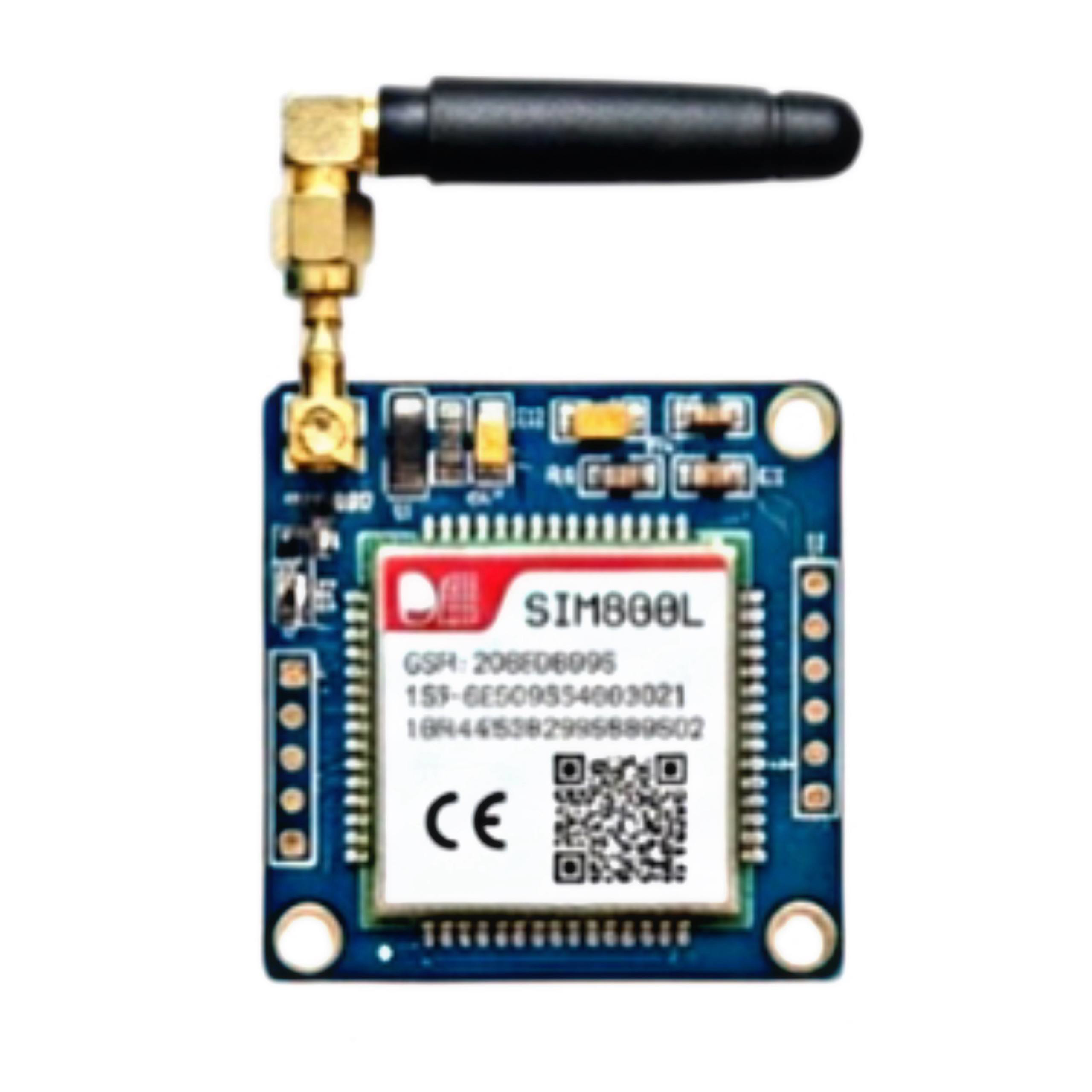
The SIM800L is a GSM/GPRS module designed for communication over cellular networks. Manufactured by Arduino with the part ID "UNO," this module supports SMS, voice calls, and data transmission. Its compact size and versatile functionality make it an excellent choice for IoT applications, remote monitoring, and embedded systems requiring cellular connectivity.
Explore Projects Built with sim800L


Explore Projects Built with sim800L
Common Applications
- Internet of Things (IoT) devices
- Remote monitoring and control systems
- SMS-based alert systems
- Voice call-enabled embedded projects
- GPS tracking systems (when paired with GPS modules)
Technical Specifications
Key Technical Details
| Parameter | Value |
|---|---|
| Operating Voltage | 3.7V to 4.2V |
| Recommended Supply Voltage | 4.0V |
| Operating Current | 0.2A (idle), up to 2A (during transmission) |
| Frequency Bands | GSM 850/900/1800/1900 MHz |
| Communication Protocols | AT Commands over UART |
| Data Transmission | GPRS Class 12, up to 85.6 kbps |
| SIM Card Support | Micro SIM |
| Dimensions | 25mm x 23mm x 3mm |
Pin Configuration and Descriptions
| Pin Name | Pin Number | Description |
|---|---|---|
| VCC | 1 | Power input (3.7V to 4.2V) |
| GND | 2 | Ground |
| RXD | 3 | UART Receive Pin (connect to TX of MCU) |
| TXD | 4 | UART Transmit Pin (connect to RX of MCU) |
| RST | 5 | Reset pin (active low) |
| NET | 6 | Network status LED (blinks to indicate status) |
Usage Instructions
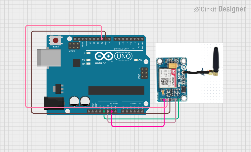
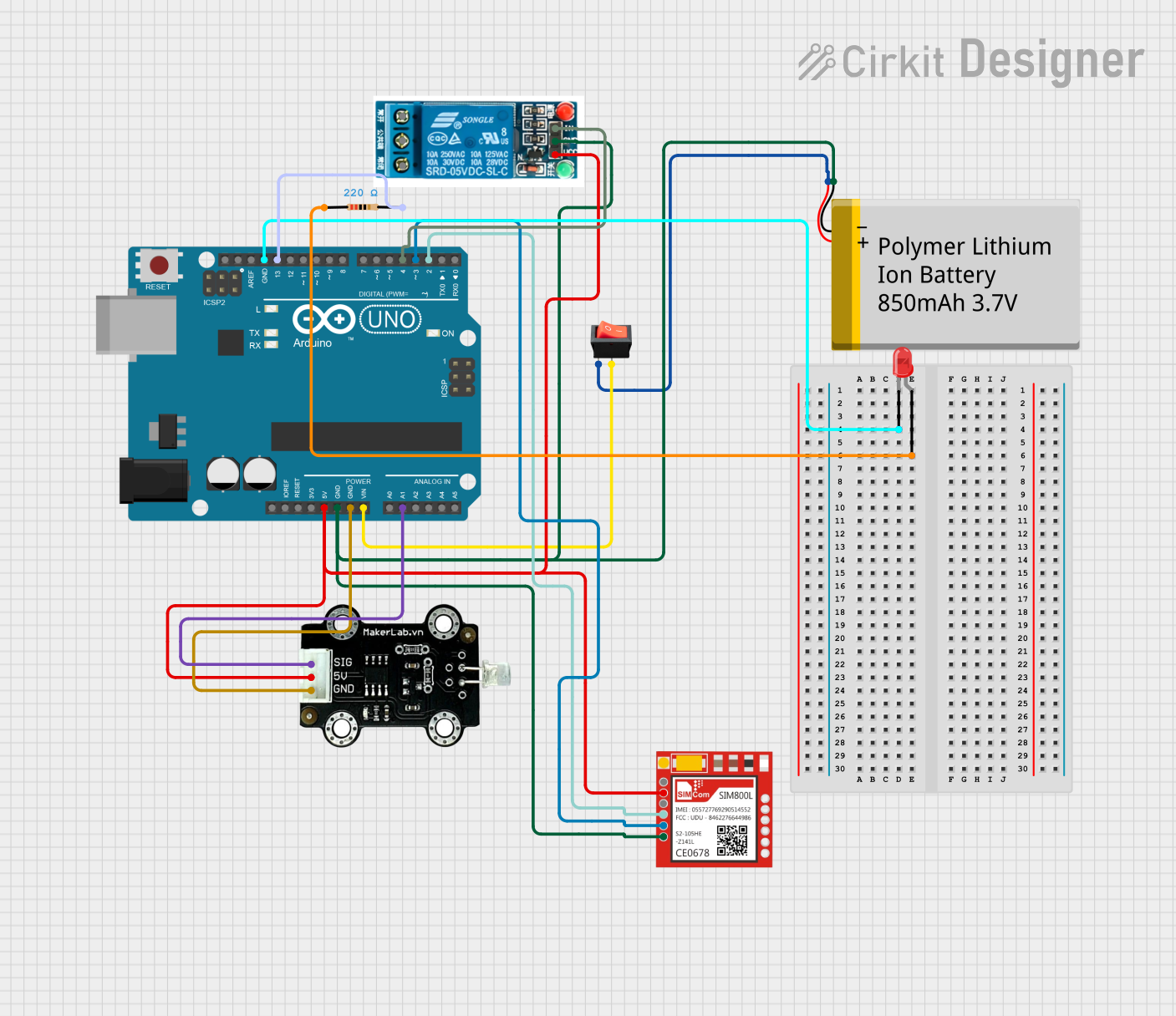
How to Use the SIM800L in a Circuit
- Power Supply: Ensure a stable power supply of 4.0V. Use a low-dropout regulator if your source voltage exceeds this range. The module can draw up to 2A during transmission, so ensure your power source can handle this.
- Connections:
- Connect the
VCCpin to a 4.0V power source. - Connect the
GNDpin to the ground of your circuit. - Connect the
TXDpin of the SIM800L to theRXpin of your Arduino UNO. - Connect the
RXDpin of the SIM800L to theTXpin of your Arduino UNO. - Optionally, connect the
RSTpin to a GPIO pin of the Arduino for manual resets.
- Connect the
- Antenna: Attach an external antenna to the module for better signal reception.
- SIM Card: Insert a micro SIM card into the SIM800L module.
Important Considerations
- Voltage Levels: The SIM800L operates at 3.3V logic levels. Use a voltage divider or level shifter if your microcontroller operates at 5V logic.
- Power Stability: Use capacitors (e.g., 1000µF) near the power input to handle voltage drops during high current draw.
- Antenna Placement: Place the antenna away from other components to avoid interference.
Example Code for Arduino UNO
Below is an example of how to send an SMS using the SIM800L module with an Arduino UNO:
#include <SoftwareSerial.h>

// Define RX and TX pins for SoftwareSerial
SoftwareSerial SIM800L(10, 11); // RX = Pin 10, TX = Pin 11

void setup() {
  // Initialize serial communication
  Serial.begin(9600); // For debugging
  SIM800L.begin(9600); // For SIM800L communication

  // Wait for the module to initialize
  delay(1000);
  Serial.println("Initializing SIM800L...");

  // Send AT command to check communication
  SIM800L.println("AT");
  delay(1000);
  while (SIM800L.available()) {
    Serial.write(SIM800L.read());
  }

  // Set SMS text mode
  SIM800L.println("AT+CMGF=1"); // Set SMS to text mode
  delay(1000);

  // Send SMS
  SIM800L.println("AT+CMGS=\"+1234567890\""); // Replace with recipient's number
  delay(1000);
  SIM800L.println("Hello from SIM800L!"); // Message content
  delay(1000);
  SIM800L.write(26); // Send Ctrl+Z to indicate end of message
  delay(5000);

  Serial.println("SMS sent!");
}

void loop() {
  // No actions in loop
}
Notes:
- Replace
+1234567890with the recipient's phone number. - Ensure the SIM card has sufficient balance for sending SMS.
Troubleshooting and FAQs
Common Issues and Solutions
Module Not Responding to AT Commands:
- Ensure the power supply is stable and within the recommended range.
- Check the RX and TX connections between the SIM800L and Arduino.
- Verify that the baud rate in the code matches the module's default baud rate (9600).
Frequent Restarts or Unstable Operation:
- Use a capacitor (e.g., 1000µF) near the power input to handle voltage drops.
- Ensure the power source can supply at least 2A during transmission.
No Network Connection:
- Check the SIM card for proper insertion and activation.
- Ensure the antenna is securely connected and placed in an area with good signal strength.
- Use the
AT+CSQcommand to check signal quality (values above 10 are acceptable).
SMS Not Sending:
- Verify the recipient's phone number format (e.g., include the country code).
- Ensure the SIM card has sufficient balance or SMS credits.
FAQs
Q: Can the SIM800L work with 5V logic levels?
A: No, the SIM800L operates at 3.3V logic levels. Use a voltage divider or level shifter for compatibility with 5V microcontrollers.
Q: What is the maximum data rate for GPRS?
A: The SIM800L supports GPRS Class 12 with a maximum data rate of 85.6 kbps.
Q: How can I check the network signal strength?
A: Use the AT+CSQ command. The response will indicate the signal strength, with values above 10 being acceptable.
Q: Can I use the SIM800L for GPS tracking?
A: The SIM800L does not have built-in GPS functionality, but it can be paired with a GPS module for tracking applications.
Q: What type of antenna should I use?
A: Use a GSM antenna compatible with the 850/900/1800/1900 MHz frequency bands for optimal performance.