How to Use JST XH 4P Female: Examples, Pinouts, and Specs
Introduction
The JST XH 4P Female connector is a 4-pin female connector widely used in electronic circuits for connecting wires. It features a compact design and a reliable locking mechanism, ensuring secure and stable connections. This connector is part of the JST XH series, known for its durability and ease of use. It is commonly used in applications such as battery connections, PCB interfaces, and small electronic devices.
Explore Projects Built with JST XH 4P Female
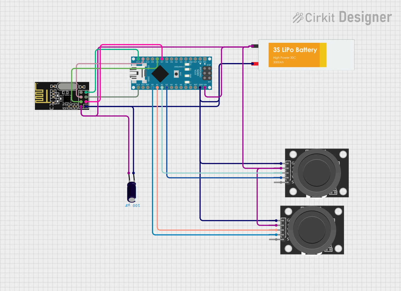


Explore Projects Built with JST XH 4P Female
Common Applications and Use Cases
- Battery pack connections in RC models, drones, and robotics
- Power and signal connections in small electronic devices
- PCB-to-wire connections in consumer electronics
- LED strip connections and other low-power applications
Technical Specifications
The JST XH 4P Female connector is designed to meet the needs of compact and reliable wire-to-board or wire-to-wire connections. Below are its key technical details:
Key Technical Details
- Number of Pins: 4
- Pitch (Pin Spacing): 2.5 mm
- Rated Voltage: 250V AC/DC
- Rated Current: 3A (maximum)
- Contact Resistance: ≤ 10 mΩ
- Insulation Resistance: ≥ 1000 MΩ
- Operating Temperature Range: -25°C to +85°C
- Material:
- Housing: Nylon 66 (UL94V-0 flame-retardant)
- Contacts: Phosphor bronze with tin plating
- Wire Gauge Compatibility: 22-28 AWG
Pin Configuration and Descriptions
The JST XH 4P Female connector has four pins, each corresponding to a specific connection. Below is the pinout description:
| Pin Number | Description | Typical Use |
|---|---|---|
| 1 | VCC (Power Supply) | Positive voltage input |
| 2 | GND (Ground) | Ground connection |
| 3 | Signal/Data Line 1 | Data or control signal |
| 4 | Signal/Data Line 2 | Data or control signal |
Note: The pin configuration may vary depending on the specific application. Always refer to the circuit design or datasheet for proper wiring.
Usage Instructions
The JST XH 4P Female connector is straightforward to use, but proper handling and wiring are essential for optimal performance. Follow the steps below to use this connector in your circuit:
How to Use the Component in a Circuit
Prepare the Wires:
- Strip the insulation from the wires to expose approximately 3-5 mm of the conductor.
- Ensure the wire gauge is compatible with the connector (22-28 AWG).
Crimp the Contacts:
- Use a crimping tool to attach the metal contacts (pins) to the stripped wires.
- Ensure the crimp is secure to avoid loose connections.
Insert the Contacts into the Housing:
- Push the crimped contacts into the connector housing until they click into place.
- Verify that the contacts are fully seated and locked.
Connect to the Male Counterpart:
- Align the JST XH 4P Female connector with the corresponding male connector.
- Push the connectors together until the locking mechanism clicks.
Verify the Connection:
- Check the connection for stability and ensure the wires are not under tension.
Important Considerations and Best Practices
- Avoid Overcurrent: Do not exceed the rated current of 3A to prevent overheating or damage.
- Secure the Wires: Use cable ties or strain relief to prevent stress on the wires and connector.
- Polarity Check: Double-check the polarity and pin configuration before powering the circuit.
- Use Proper Tools: Always use a compatible crimping tool for reliable connections.
Example: Connecting to an Arduino UNO
The JST XH 4P Female connector can be used to connect sensors or modules to an Arduino UNO. Below is an example of how to connect a sensor with a JST XH 4P interface:
Wiring Diagram
- Pin 1 (VCC): Connect to the Arduino's 5V pin.
- Pin 2 (GND): Connect to the Arduino's GND pin.
- Pin 3 (Signal 1): Connect to a digital input pin (e.g., D2).
- Pin 4 (Signal 2): Connect to another digital input pin (e.g., D3).
Sample Arduino Code
// Example code for reading data from a sensor connected via JST XH 4P

const int signalPin1 = 2; // Pin connected to Signal/Data Line 1
const int signalPin2 = 3; // Pin connected to Signal/Data Line 2

void setup() {
  pinMode(signalPin1, INPUT); // Set Signal 1 as input
  pinMode(signalPin2, INPUT); // Set Signal 2 as input
  Serial.begin(9600); // Initialize serial communication
}

void loop() {
  int data1 = digitalRead(signalPin1); // Read data from Signal 1
  int data2 = digitalRead(signalPin2); // Read data from Signal 2

  // Print the data to the Serial Monitor
  Serial.print("Signal 1: ");
  Serial.println(data1);
  Serial.print("Signal 2: ");
  Serial.println(data2);

  delay(500); // Wait for 500ms before the next reading
}
Troubleshooting and FAQs
Common Issues and Solutions
Loose Connections:
- Issue: The connector feels loose or disconnects easily.
- Solution: Ensure the contacts are fully inserted into the housing and the locking mechanism is engaged.
Overheating:
- Issue: The connector becomes hot during operation.
- Solution: Check the current draw of the circuit and ensure it does not exceed 3A. Use thicker wires if necessary.
Signal Interference:
- Issue: Data signals are noisy or unreliable.
- Solution: Use shielded cables for signal lines and keep power and signal wires separate.
Incorrect Wiring:
- Issue: The circuit does not function as expected.
- Solution: Double-check the pin configuration and wiring against the circuit diagram.
FAQs
Q: Can the JST XH 4P Female connector handle high-power applications?
A: No, this connector is designed for low-power applications with a maximum current rating of 3A.Q: Is the connector reusable?
A: The housing is reusable, but the crimped contacts may need to be replaced if removed.Q: Can I solder wires directly to the connector?
A: It is not recommended to solder wires directly, as this may damage the housing or compromise the connection.Q: What tools are required for crimping?
A: A compatible crimping tool designed for JST XH series connectors is required for reliable crimps.
By following this documentation, you can effectively use the JST XH 4P Female connector in your electronic projects.