
How to Use DC3010-01 Control Board: Examples, Pinouts, and Specs
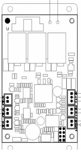
 Design with DC3010-01 Control Board in Cirkit Designer
Introduction
The DC3010-01 Control Board, manufactured by Generic, is a versatile and reliable control board designed for managing and regulating various electronic functions in a circuit. It is commonly used in automation, robotics, and control systems where precise control and efficient operation are required. The board is compact, easy to integrate, and supports a wide range of applications, making it a popular choice for both hobbyists and professionals.
Explore Projects Built with DC3010-01 Control Board
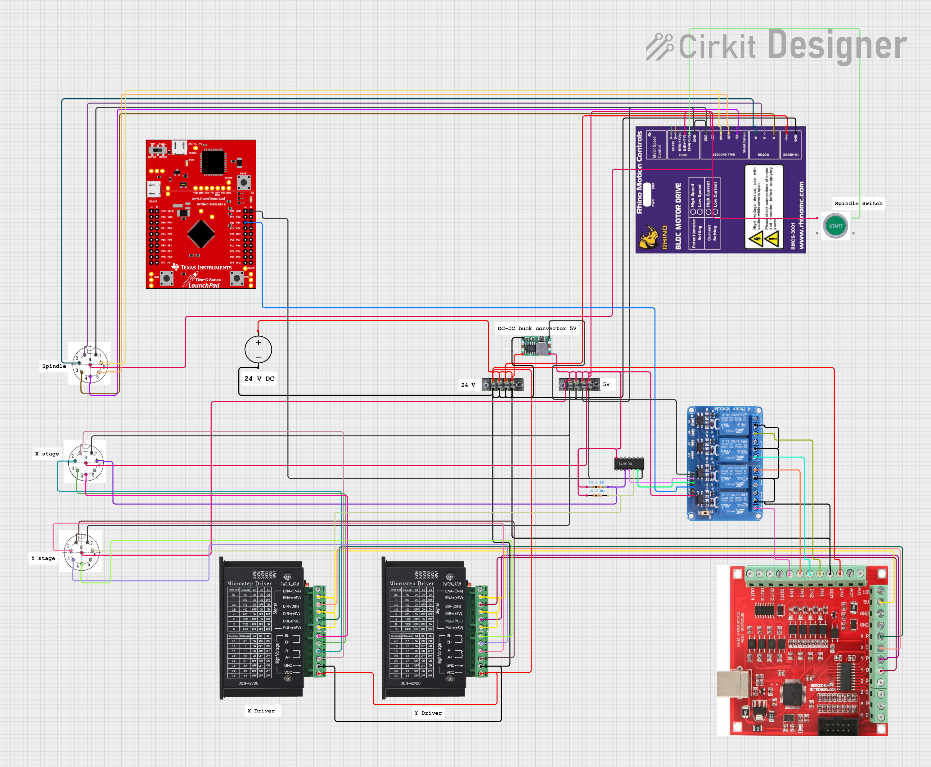 Open Project in Cirkit Designer
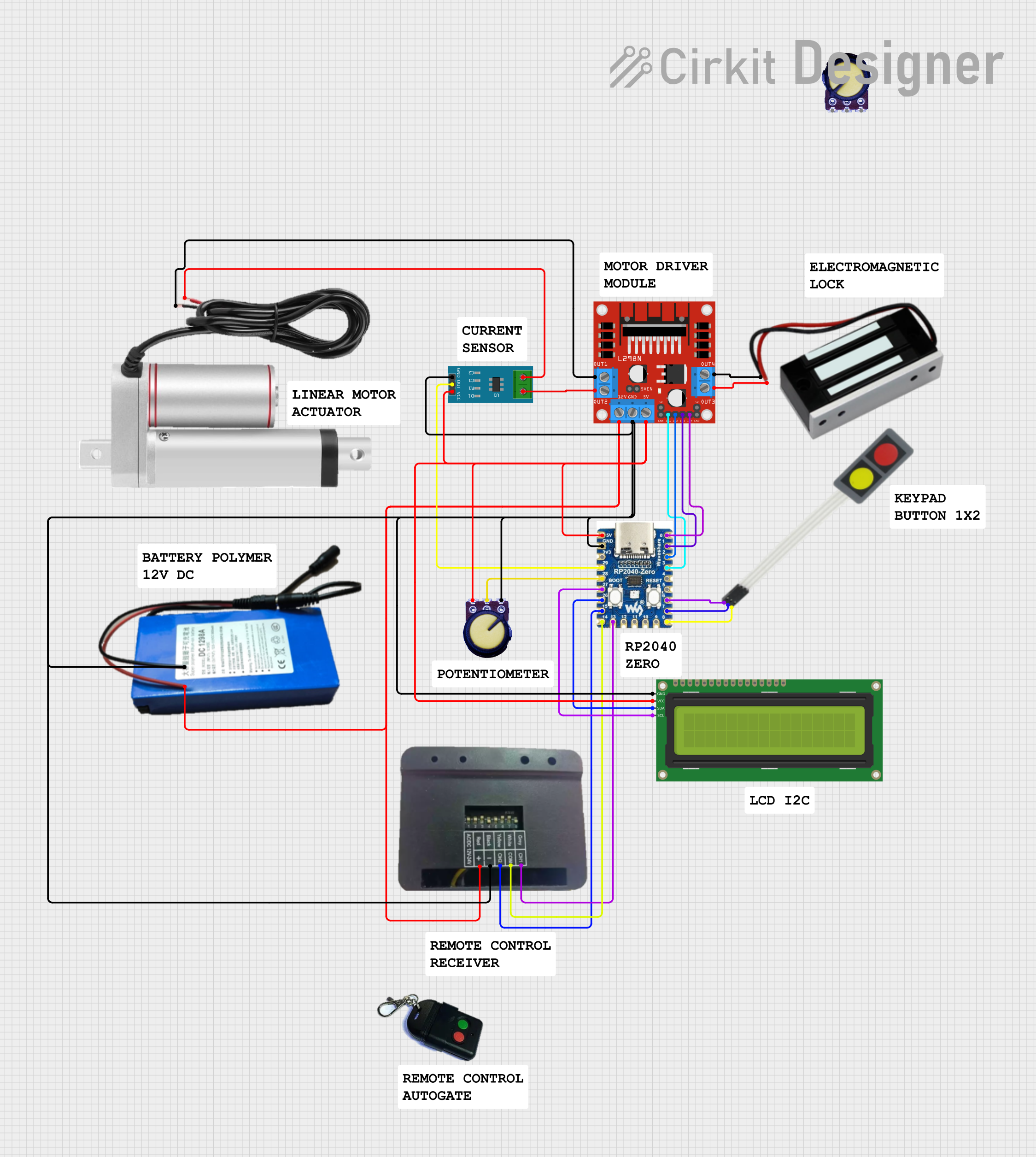 Open Project in Cirkit Designer
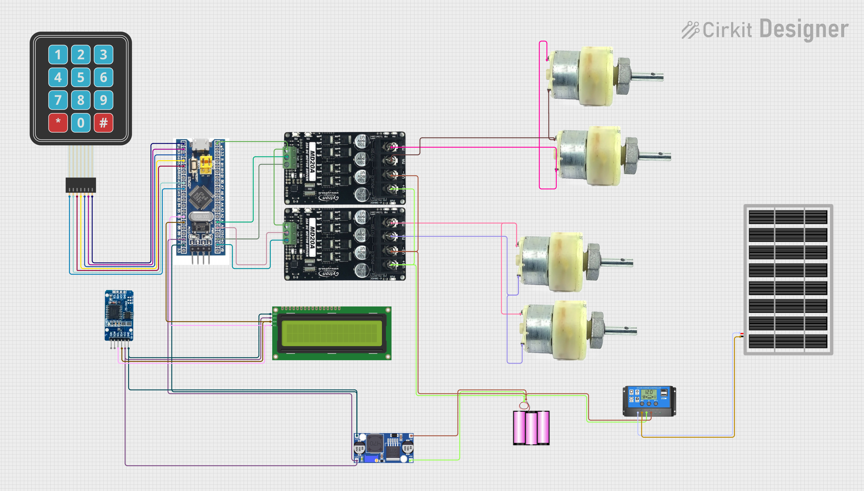 Open Project in Cirkit Designer
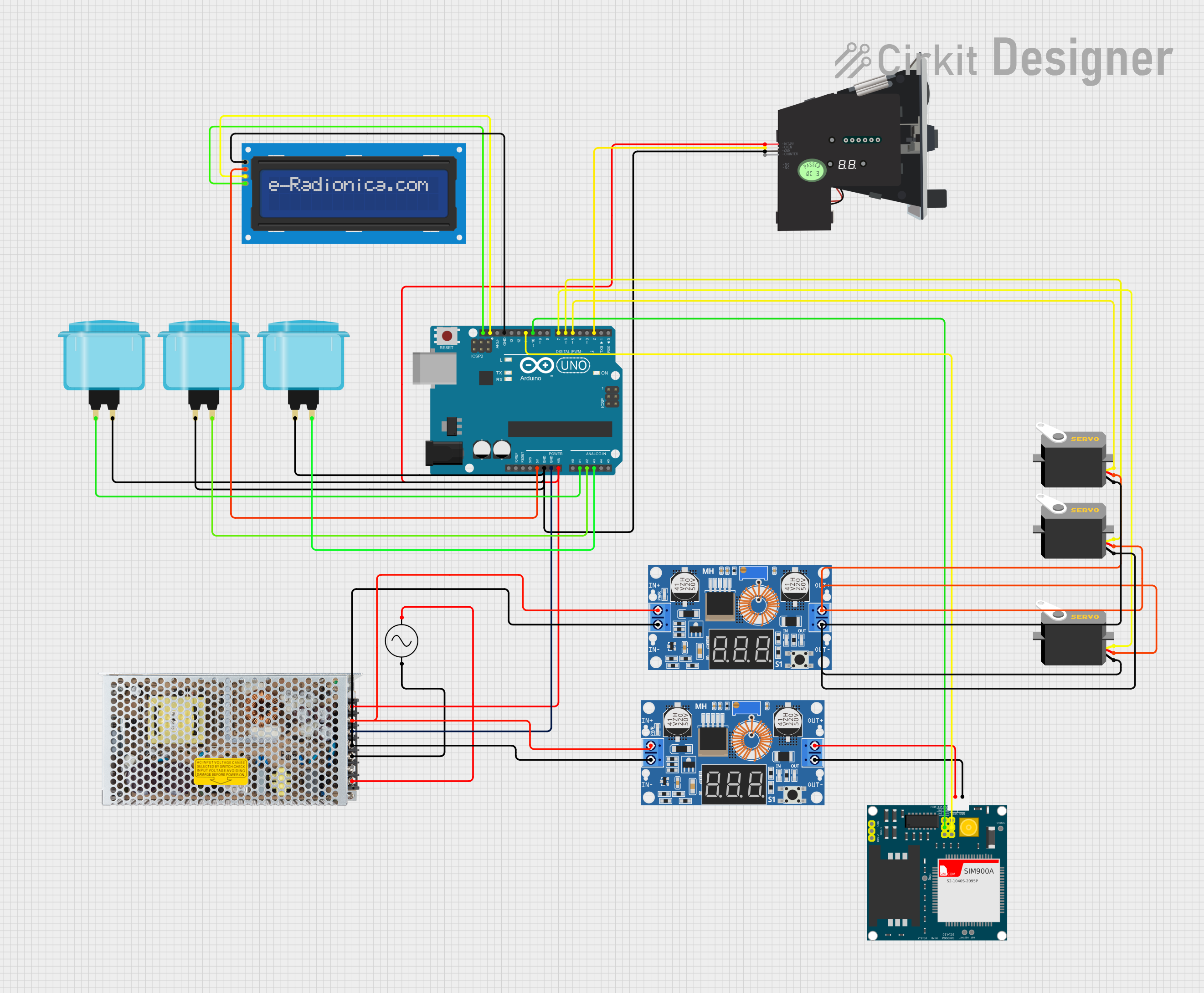 Open Project in Cirkit Designer
Explore Projects Built with DC3010-01 Control Board
Open Project in Cirkit DesignerOpen Project in Cirkit DesignerOpen Project in Cirkit DesignerOpen Project in Cirkit DesignerCommon Applications
- Industrial automation systems
- Robotics and motor control
- Home automation projects
- Power management in electronic devices
- Prototyping and development of control systems
Technical Specifications
The following table outlines the key technical specifications of the DC3010-01 Control Board:
| Parameter | Specification |
|---|---|
| Operating Voltage | 5V to 24V DC |
| Maximum Current Output | 10A |
| Control Signal Input | 3.3V or 5V logic levels |
| Dimensions | 50mm x 40mm x 15mm |
| Operating Temperature | -20°C to 85°C |
| Communication Protocol | PWM, Analog Input, or Digital Input |
Pin Configuration and Descriptions
The DC3010-01 Control Board features a simple pin layout for easy integration. Below is the pin configuration:
| Pin | Name | Description |
|---|---|---|
| 1 | VIN | Power input pin (5V to 24V DC) |
| 2 | GND | Ground connection |
| 3 | IN1 | Control signal input 1 (PWM or digital signal) |
| 4 | IN2 | Control signal input 2 (optional, for dual-channel control) |
| 5 | OUT+ | Positive output terminal for the load |
| 6 | OUT- | Negative output terminal for the load |
| 7 | STATUS_LED | Status indicator LED pin (active HIGH) |
| 8 | NC | Not connected (reserved for future use) |
Usage Instructions
How to Use the DC3010-01 Control Board in a Circuit
- Power Supply: Connect the VIN pin to a DC power source (5V to 24V) and the GND pin to the ground of the power source.
- Control Signal: Use a microcontroller (e.g., Arduino UNO) or other control devices to send a PWM or digital signal to the IN1 pin. If dual-channel control is required, connect a second signal to the IN2 pin.
- Load Connection: Connect the load (e.g., motor, LED strip, or other devices) to the OUT+ and OUT- terminals.
- Status Monitoring: Optionally, connect an LED to the STATUS_LED pin to monitor the board's operational status.
Important Considerations and Best Practices
- Ensure the input voltage does not exceed the specified range (5V to 24V) to avoid damage to the board.
- Use appropriate heat dissipation methods (e.g., heatsinks) if operating at high currents for extended periods.
- Verify the polarity of the power supply and load connections to prevent reverse polarity damage.
- For PWM control, use a frequency between 500Hz and 20kHz for optimal performance.
Example: Using the DC3010-01 with an Arduino UNO
Below is an example of how to control the DC3010-01 Control Board using an Arduino UNO to drive a motor with PWM:
// Example code to control the DC3010-01 Control Board with Arduino UNO

const int controlPin = 9; // PWM pin connected to IN1 on the DC3010-01
const int statusPin = 13; // Optional: Arduino's built-in LED for status

void setup() {
  pinMode(controlPin, OUTPUT); // Set the control pin as an output
  pinMode(statusPin, OUTPUT);  // Set the status pin as an output
}

void loop() {
  // Gradually increase motor speed
  for (int speed = 0; speed <= 255; speed++) {
    analogWrite(controlPin, speed); // Send PWM signal to control motor speed
    digitalWrite(statusPin, HIGH); // Turn on status LED
    delay(20); // Wait for 20ms
  }

  // Gradually decrease motor speed
  for (int speed = 255; speed >= 0; speed--) {
    analogWrite(controlPin, speed); // Send PWM signal to control motor speed
    digitalWrite(statusPin, LOW);  // Turn off status LED
    delay(20); // Wait for 20ms
  }
}
Troubleshooting and FAQs
Common Issues and Solutions
Board Not Powering On
- Cause: Incorrect power supply voltage or loose connections.
- Solution: Verify that the input voltage is within the 5V to 24V range and check all connections.
Load Not Responding
- Cause: Incorrect wiring or insufficient control signal.
- Solution: Ensure the load is properly connected to the OUT+ and OUT- terminals. Check the control signal voltage and frequency.
Overheating
- Cause: High current draw or inadequate heat dissipation.
- Solution: Use a heatsink or cooling fan if operating at high currents for extended periods.
Status LED Not Working
- Cause: Faulty connection or damaged LED.
- Solution: Check the wiring to the STATUS_LED pin and replace the LED if necessary.
FAQs
Can the DC3010-01 Control Board handle AC loads?
- No, the board is designed for DC loads only. Using it with AC loads may damage the board.
What is the maximum PWM frequency supported?
- The board supports PWM frequencies up to 20kHz for optimal performance.
Can I use the board with a Raspberry Pi?
- Yes, the board can be controlled using a Raspberry Pi's GPIO pins, provided the control signal voltage is 3.3V or 5V.
Is the board protected against reverse polarity?
- No, the board does not have built-in reverse polarity protection. Ensure correct polarity when connecting the power supply and load.
This concludes the documentation for the DC3010-01 Control Board. For further assistance, refer to the manufacturer's support resources or community forums.