Cirkit Designer Logo
Cirkit Designer
Your all-in-one circuit design IDE
Home / 
Component Documentation

How to Use Sound Sensor: Examples, Pinouts, and Specs

Image of Sound Sensor
Cirkit Designer LogoDesign with Sound Sensor in Cirkit Designer

Introduction

A sound sensor is an electronic device that detects sound levels in the environment and converts them into electrical signals. These sensors are commonly used in various applications such as noise level monitoring, security systems, and interactive projects that respond to voice commands or other sounds. They are particularly popular in hobbyist projects with microcontrollers like the Arduino UNO.

Explore Projects Built with Sound Sensor

Use Cirkit Designer to design, explore, and prototype these projects online. Some projects support real-time simulation. Click "Open Project" to start designing instantly!
Arduino UNO-Based Multi-Sensor Health and Environmental Monitoring System with Bluetooth Connectivity
Image of Sleep Appnea Monitoring System: A project utilizing Sound Sensor in a practical application
This is a multi-functional sensor and communication circuit built around an Arduino UNO. It is designed to collect environmental and health-related data, process and respond to voice commands, and communicate wirelessly. Output feedback is provided through LEDs and a buzzer.
Cirkit Designer LogoOpen Project in Cirkit Designer
Arduino 101 Sound-Activated Piezo Speaker System
Image of noise detector: A project utilizing Sound Sensor in a practical application
This circuit features an Arduino 101 microcontroller connected to a sound sensor and a piezo speaker. The sound sensor's output is connected to the Arduino's A0 analog input, allowing the microcontroller to process audio signal levels. The piezo speaker is connected to digital pin D8 and ground (GND), enabling the Arduino to generate audio signals or feedback based on the sensor input.
Cirkit Designer LogoOpen Project in Cirkit Designer
Arduino-Controlled Ultrasonic Distance Measurement with Audio Feedback
Image of sound project: A project utilizing Sound Sensor in a practical application
This circuit features an Arduino UNO microcontroller interfaced with an HC-SR04 Ultrasonic Sensor and a DFPlayer MINI MP3 module connected to a loudspeaker. The Arduino controls the ultrasonic sensor to measure distances and uses the DFPlayer MINI to play audio through the loudspeaker. The purpose of the circuit is likely to detect objects at certain distances and respond with audio playback, potentially for an interactive installation or alert system.
Cirkit Designer LogoOpen Project in Cirkit Designer
Arduino Uno R3 Sound-Activated Relay Switch
Image of clap activated lamp: A project utilizing Sound Sensor in a practical application
This circuit is designed to detect sound through a sound sensor and trigger a relay based on the detected sound signal. The sound sensor is powered by the Arduino Uno R3 and sends a digital signal to one of the Arduino's digital pins when sound is detected. The Arduino then controls the relay, which can switch a separate circuit that could be connected to its normally open (NO) or normally closed (NC) contacts.
Cirkit Designer LogoOpen Project in Cirkit Designer

Explore Projects Built with Sound Sensor

Use Cirkit Designer to design, explore, and prototype these projects online. Some projects support real-time simulation. Click "Open Project" to start designing instantly!
Image of Sleep Appnea Monitoring System: A project utilizing Sound Sensor in a practical application
Arduino UNO-Based Multi-Sensor Health and Environmental Monitoring System with Bluetooth Connectivity
This is a multi-functional sensor and communication circuit built around an Arduino UNO. It is designed to collect environmental and health-related data, process and respond to voice commands, and communicate wirelessly. Output feedback is provided through LEDs and a buzzer.
Cirkit Designer LogoOpen Project in Cirkit Designer
Image of noise detector: A project utilizing Sound Sensor in a practical application
Arduino 101 Sound-Activated Piezo Speaker System
This circuit features an Arduino 101 microcontroller connected to a sound sensor and a piezo speaker. The sound sensor's output is connected to the Arduino's A0 analog input, allowing the microcontroller to process audio signal levels. The piezo speaker is connected to digital pin D8 and ground (GND), enabling the Arduino to generate audio signals or feedback based on the sensor input.
Cirkit Designer LogoOpen Project in Cirkit Designer
Image of sound project: A project utilizing Sound Sensor in a practical application
Arduino-Controlled Ultrasonic Distance Measurement with Audio Feedback
This circuit features an Arduino UNO microcontroller interfaced with an HC-SR04 Ultrasonic Sensor and a DFPlayer MINI MP3 module connected to a loudspeaker. The Arduino controls the ultrasonic sensor to measure distances and uses the DFPlayer MINI to play audio through the loudspeaker. The purpose of the circuit is likely to detect objects at certain distances and respond with audio playback, potentially for an interactive installation or alert system.
Cirkit Designer LogoOpen Project in Cirkit Designer
Image of clap activated lamp: A project utilizing Sound Sensor in a practical application
Arduino Uno R3 Sound-Activated Relay Switch
This circuit is designed to detect sound through a sound sensor and trigger a relay based on the detected sound signal. The sound sensor is powered by the Arduino Uno R3 and sends a digital signal to one of the Arduino's digital pins when sound is detected. The Arduino then controls the relay, which can switch a separate circuit that could be connected to its normally open (NO) or normally closed (NC) contacts.
Cirkit Designer LogoOpen Project in Cirkit Designer

Technical Specifications

Key Technical Details

  • Operating Voltage: Typically 3.3V to 5V
  • Current Consumption: Varies with model, often in the microampere (µA) range
  • Frequency Range: Generally sensitive to audio frequencies (20Hz to 20kHz)
  • Output: Analog voltage signal relative to sound intensity

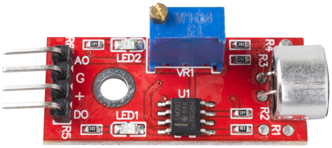
Pin Configuration and Descriptions

Pin Name Description
VCC Power supply (3.3V to 5V)
GND Ground
A0 Analog output (proportional to sound level)
D0 Digital output (sound detection threshold)

Usage Instructions

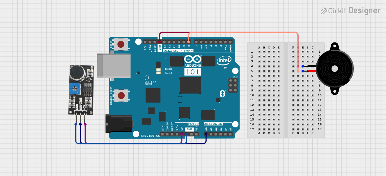
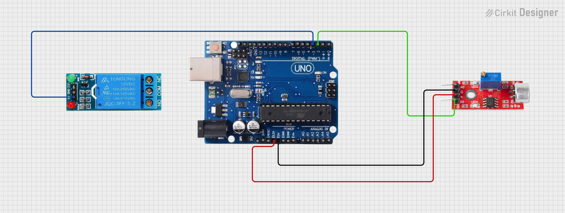
Connecting to a Circuit

  1. Connect the VCC pin to the 5V output on the Arduino UNO.
  2. Connect the GND pin to one of the GND pins on the Arduino UNO.
  3. Connect the A0 pin to any of the analog input pins (A0-A5) on the Arduino UNO.
  4. (Optional) Connect the D0 pin to a digital input pin if you wish to use the threshold feature.

Important Considerations and Best Practices

  • Ensure that the operating voltage of the sound sensor matches that of the microcontroller to prevent damage.
  • Place the sensor away from noise sources like motors or high-frequency electronics to avoid interference.
  • Use proper decoupling capacitors close to the sensor's power supply pins to minimize power supply noise.

Example Arduino Code

// Define the sound sensor pin
const int soundSensorPin = A0;

void setup() {
  // Initialize serial communication at 9600 baud rate
  Serial.begin(9600);
}

void loop() {
  // Read the analog value from the sound sensor
  int sensorValue = analogRead(soundSensorPin);
  
  // Convert the reading to a voltage level
  float voltage = sensorValue * (5.0 / 1023.0);
  
  // Print the voltage level to the Serial Monitor
  Serial.print("Voltage: ");
  Serial.println(voltage);
  
  // Wait for a short period before reading again
  delay(200);
}

Troubleshooting and FAQs

Common Issues

  • No Output: Ensure that the sensor is properly powered and that the pins are correctly connected.
  • Erratic Readings: Check for loose connections or interference from nearby electronic devices.
  • Low Sensitivity: Adjust the sensitivity potentiometer on the sensor, if available.

Solutions and Tips for Troubleshooting

  • If the sensor is not responding, verify that the power supply is within the specified voltage range.
  • For digital output mode, you may need to calibrate the threshold level using the onboard potentiometer.
  • Use shielded cables for connections to reduce noise and interference.

FAQs

Q: Can the sound sensor differentiate between different sounds or frequencies? A: Standard sound sensors output a voltage proportional to the sound intensity and do not differentiate between frequencies. For frequency analysis, additional processing, such as a Fast Fourier Transform (FFT), is required.

Q: Is it possible to use multiple sound sensors with an Arduino UNO? A: Yes, multiple sound sensors can be connected to different analog pins on the Arduino UNO. Ensure that each sensor has its own dedicated analog pin.

Q: How can I improve the accuracy of the sound sensor? A: To improve accuracy, calibrate the sensor in the environment where it will be used, and consider using averaging or filtering techniques to smooth out the readings.