
How to Use CMA3000-A01: Examples, Pinouts, and Specs
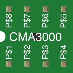
 Design with CMA3000-A01 in Cirkit Designer
Introduction
The CMA3000-A01 is a high-performance analog-to-digital converter (ADC) designed for precision measurement applications. It offers low power consumption, high resolution, and fast conversion rates, making it ideal for systems requiring accurate data acquisition. This component is widely used in industrial automation, medical devices, instrumentation, and consumer electronics where precise analog signal conversion is critical.
Explore Projects Built with CMA3000-A01
 Open Project in Cirkit Designer
 Open Project in Cirkit Designer
 Open Project in Cirkit Designer
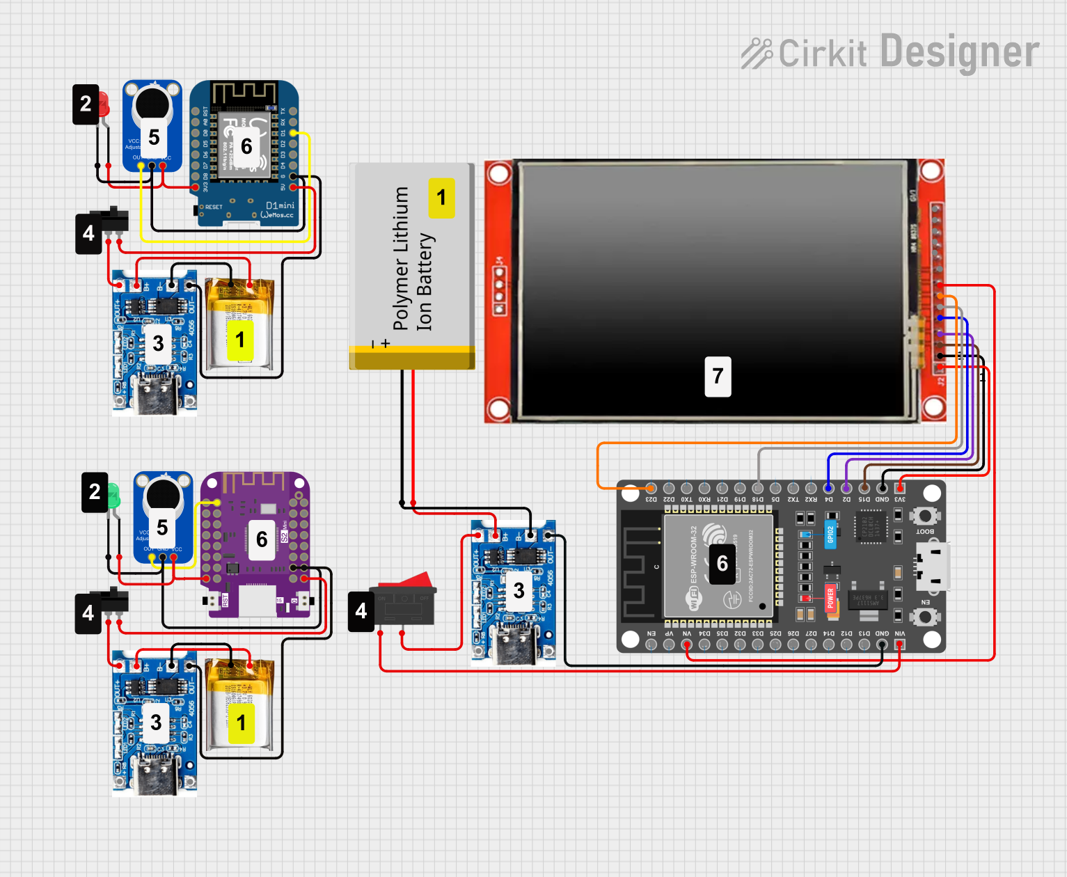 Open Project in Cirkit Designer
Explore Projects Built with CMA3000-A01
Open Project in Cirkit DesignerOpen Project in Cirkit DesignerOpen Project in Cirkit DesignerOpen Project in Cirkit DesignerCommon Applications:
- Industrial automation and control systems
- Medical instrumentation (e.g., ECG, blood pressure monitors)
- Data acquisition systems
- Consumer electronics requiring high-resolution ADCs
- Environmental monitoring devices
Technical Specifications
Key Technical Details:
| Parameter | Value |
|---|---|
| Supply Voltage (VDD) | 2.0V to 3.6V |
| Resolution | 16-bit |
| Maximum Sampling Rate | 100 kSPS (kilo-samples per second) |
| Input Voltage Range | 0V to VDD |
| Power Consumption | 1.2 mW (typical at 3.0V) |
| Operating Temperature | -40°C to +85°C |
| Communication Interface | SPI |
| Package Type | LGA-12 (3 mm x 3 mm) |
Pin Configuration and Descriptions:
| Pin Number | Pin Name | Description |
|---|---|---|
| 1 | VDD | Positive power supply (2.0V to 3.6V). |
| 2 | GND | Ground connection. |
| 3 | CS | Chip Select (active low). |
| 4 | SCLK | Serial Clock input for SPI communication. |
| 5 | MOSI | Master Out Slave In (data input to the ADC). |
| 6 | MISO | Master In Slave Out (data output from the ADC). |
| 7 | IN+ | Positive analog input. |
| 8 | IN- | Negative analog input. |
| 9 | REF+ | Positive reference voltage input. |
| 10 | REF- | Negative reference voltage input. |
| 11 | NC | No connection (leave unconnected). |
| 12 | NC | No connection (leave unconnected). |
Usage Instructions
How to Use the CMA3000-A01 in a Circuit:
- Power Supply: Connect the VDD pin to a stable power source within the range of 2.0V to 3.6V. Connect the GND pin to the ground of the circuit.
- Analog Inputs: Connect the analog signal to be measured to the IN+ and IN- pins. Ensure the input voltage stays within the specified range (0V to VDD).
- Reference Voltage: Provide a stable reference voltage to the REF+ and REF- pins. The reference voltage determines the full-scale range of the ADC.
- SPI Communication: Connect the SPI interface pins (CS, SCLK, MOSI, MISO) to a microcontroller or processor for data communication. Ensure proper configuration of the SPI clock polarity and phase.
- Bypass Capacitors: Place decoupling capacitors (e.g., 0.1 µF and 10 µF) close to the VDD and GND pins to reduce noise and ensure stable operation.
Important Considerations and Best Practices:
- Use a low-noise power supply to minimize interference in the ADC measurements.
- Ensure proper grounding to avoid ground loops and noise coupling.
- Use shielded cables or PCB traces for the analog input signals to reduce electromagnetic interference (EMI).
- Configure the SPI interface correctly on the microcontroller to match the ADC's communication requirements.
- Avoid exceeding the maximum input voltage range to prevent damage to the ADC.
Example Code for Arduino UNO:
Below is an example of how to interface the CMA3000-A01 with an Arduino UNO using SPI communication:
#include <SPI.h>

// Define SPI pins for the CMA3000-A01
const int CS_PIN = 10; // Chip Select pin

void setup() {
  // Initialize SPI communication
  SPI.begin();
  pinMode(CS_PIN, OUTPUT);
  digitalWrite(CS_PIN, HIGH); // Set CS pin to HIGH (inactive)

  Serial.begin(9600); // Initialize serial communication for debugging
}

void loop() {
  // Start ADC conversion and read data
  digitalWrite(CS_PIN, LOW); // Activate the ADC by pulling CS low
  byte highByte = SPI.transfer(0x00); // Send dummy byte to receive high byte
  byte lowByte = SPI.transfer(0x00);  // Send dummy byte to receive low byte
  digitalWrite(CS_PIN, HIGH); // Deactivate the ADC by pulling CS high

  // Combine high and low bytes into a 16-bit result
  int adcValue = (highByte << 8) | lowByte;

  // Print the ADC value to the serial monitor
  Serial.print("ADC Value: ");
  Serial.println(adcValue);

  delay(1000); // Wait for 1 second before the next reading
}
Notes:
- Ensure the SPI clock speed does not exceed the maximum supported by the CMA3000-A01.
- Adjust the SPI settings (e.g., clock polarity and phase) if necessary to match the ADC's requirements.
Troubleshooting and FAQs
Common Issues and Solutions:
No Data Output from the ADC:
- Ensure the SPI connections (CS, SCLK, MOSI, MISO) are correctly wired.
- Verify that the SPI settings (clock polarity, phase, and speed) match the ADC's requirements.
- Check that the CS pin is being toggled correctly during communication.
Incorrect ADC Readings:
- Confirm that the analog input voltage is within the specified range (0V to VDD).
- Verify the reference voltage is stable and within the recommended range.
- Check for noise or interference on the analog input signals.
High Noise in Measurements:
- Use proper decoupling capacitors near the VDD and GND pins.
- Ensure the analog input signals are shielded and routed away from noisy components.
- Minimize the length of the analog input traces or wires.
Device Overheating:
- Ensure the supply voltage does not exceed the maximum rating.
- Check for short circuits or excessive current draw in the circuit.
FAQs:
Q1: Can the CMA3000-A01 be used with a 5V microcontroller?
A1: Yes, but you must use level shifters or voltage dividers to interface the 3.3V SPI signals with the 5V microcontroller.
Q2: What is the maximum sampling rate of the CMA3000-A01?
A2: The maximum sampling rate is 100 kSPS.
Q3: Can I leave the NC pins unconnected?
A3: Yes, the NC (No Connection) pins should be left unconnected as they are not internally connected.
Q4: How do I calculate the input voltage from the ADC value?
A4: Use the formula:
[
V_{in} = \left(\frac{\text{ADC Value}}{2^{\text{Resolution}} - 1}\right) \times V_{ref}
]
where ( V_{ref} ) is the reference voltage.
By following this documentation, users can effectively integrate the CMA3000-A01 into their projects and troubleshoot common issues.