How to Use 4G Antenna: Examples, Pinouts, and Specs
Introduction
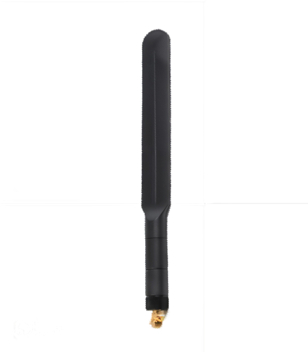
The Waveshare 4G Antenna is a high-performance antenna designed for 4G LTE communication. It is suitable for mobile devices, wireless routers, and any application requiring reliable 4G connectivity. This antenna enhances signal strength and improves communication quality in 4G LTE bands.
Explore Projects Built with 4G Antenna


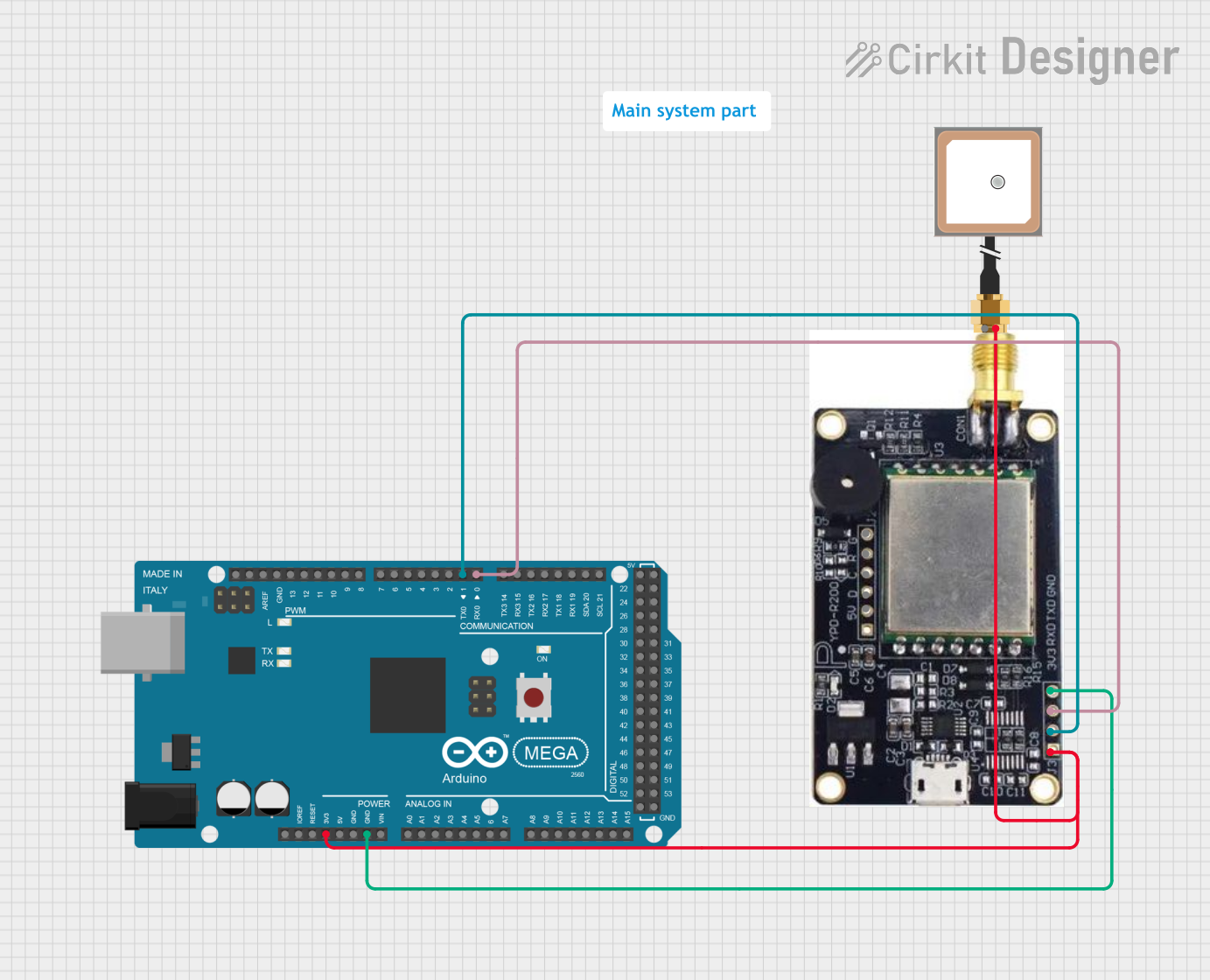

Explore Projects Built with 4G Antenna
Common Applications and Use Cases
- Mobile communication devices
- 4G LTE wireless routers
- Remote monitoring systems
- IoT devices requiring 4G connectivity
- Telemetry and remote control applications
Technical Specifications
Key Technical Details
- Frequency Range: Typically 698-960 MHz / 1710-2690 MHz
- VSWR: ≤ 2.5
- Gain: 5dBi (typical)
- Polarization: Vertical
- Impedance: 50 Ohms
- Radiation: Omni-directional
Pin Configuration and Descriptions
| Pin | Description |
|---|---|
| 1 | Antenna Main Connector (SMA) |
Usage Instructions
How to Use the Component in a Circuit
- Connection: Connect the antenna to the 4G module or device using the SMA connector. Ensure the connection is secure to prevent signal loss.
- Placement: Position the antenna vertically for optimal performance. Keep it away from metal objects and electronic interference.
- Testing: After installation, test the signal strength to ensure the antenna is functioning correctly.
Important Considerations and Best Practices
- Orientation: The antenna should be kept vertical for the best performance.
- Location: Avoid placing the antenna near metal surfaces or electronic devices that may cause interference.
- Cable Length: Use the shortest possible cable between the antenna and the device to minimize signal loss.
- Weatherproofing: If the antenna is to be used outdoors, ensure it is weatherproof or placed in a protective enclosure.
Troubleshooting and FAQs
Common Issues Users Might Face
- Poor Signal Strength: Ensure the antenna is properly connected and positioned. Check for any obstructions or sources of interference.
- Intermittent Connectivity: Verify that the antenna is not damaged and that all connections are secure.
Solutions and Tips for Troubleshooting
- Repositioning the Antenna: Sometimes simply changing the location or orientation of the antenna can significantly improve signal quality.
- Checking Connections: Loose connections can lead to poor performance. Tighten all connections and replace any worn cables.
- Avoiding Interference: Keep the antenna away from other electronic devices that may cause interference.
FAQs
Q: Can this antenna be used with any 4G device? A: The antenna is designed with a standard SMA connector, making it compatible with most 4G devices that support an external antenna.
Q: What is the range of this antenna? A: The range depends on various factors, including the device's power, the environment, and any potential obstructions. It is designed to maximize the signal strength within the operational bands.
Q: Is this antenna suitable for outdoor use? A: The antenna is capable of outdoor use, but it should be placed in a weatherproof enclosure to protect it from the elements.
Q: How can I improve the performance of my 4G antenna? A: Ensure that the antenna is positioned correctly, use a high-quality cable with minimal length, and avoid sources of interference.
Please note that this documentation is a general guide and may not cover all aspects of the Waveshare 4G Antenna. For specific questions or advanced troubleshooting, consult the manufacturer's documentation or contact their technical support.