The SparkFun Simultaneous RFID Reader - M6E Nano is a versatile and powerful ultra-high frequency (UHF) RFID reader module capable of reading multiple RFID tags concurrently. Utilizing the M6E Nano module, this reader operates in the 860 to 960 MHz UHF RFID frequency range, which is suitable for a wide range of applications including inventory management, asset tracking, and access control systems. Its compact form factor and SPI interface make it an excellent choice for embedding into electronics projects, particularly those requiring efficient and high-volume tag reading.
Explore Projects Built with SparkFun Simultaneous RFID Reader - M6E Nano
Use Cirkit Designer to design, explore, and prototype these projects online. Some projects support real-time simulation. Click "Open Project" to start designing instantly!
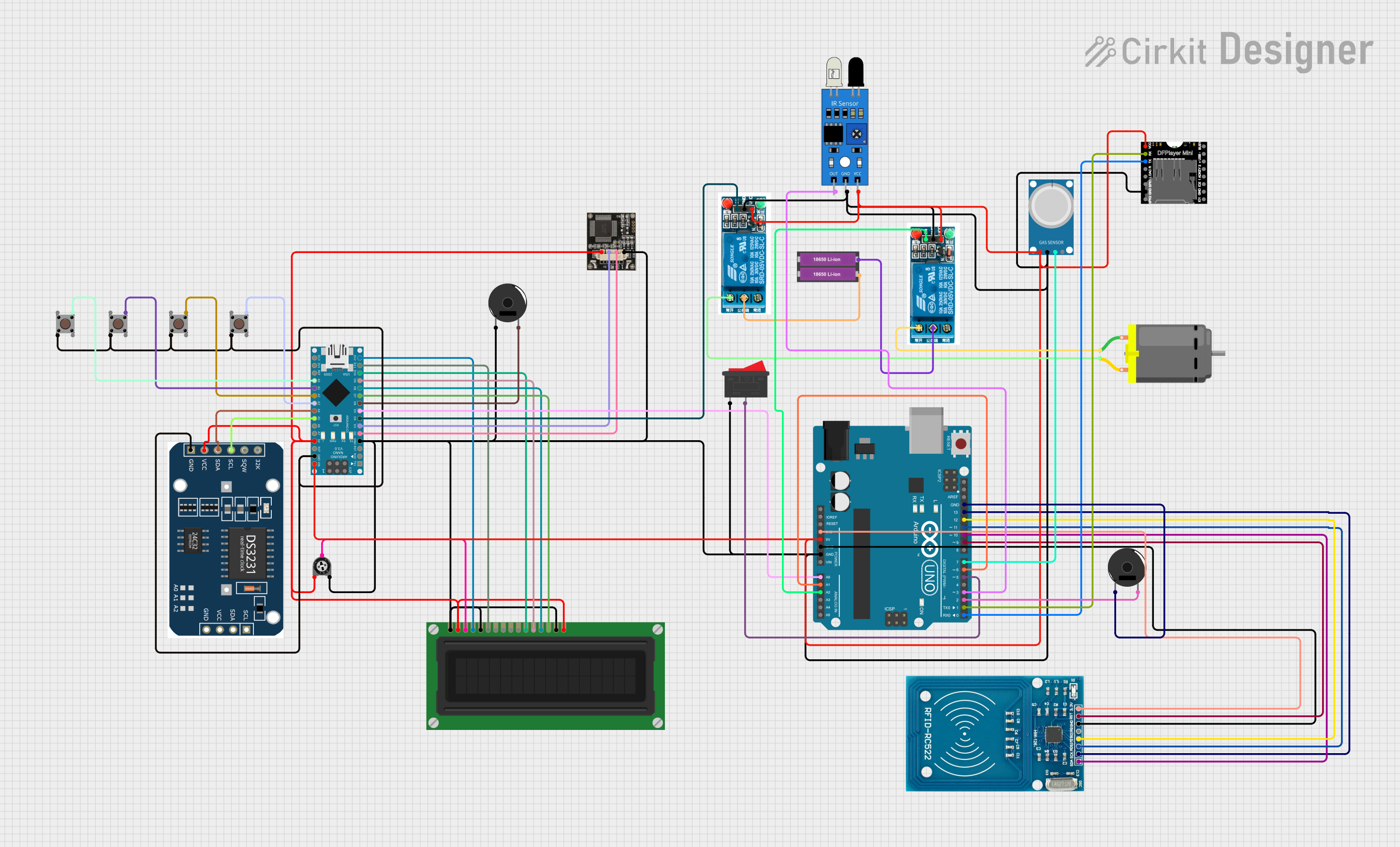
This circuit features an Arduino UNO and an Arduino Nano as the main microcontrollers, interfaced with a variety of sensors and modules including an RFID-RC522 for RFID reading, an MQ-4 gas sensor, an IR sensor, and an RTC module for real-time clock functionality. It also includes actuators such as a DC motor controlled by two 5V relays, an LCD display for user interface, and piezo buzzers for audio feedback. The circuit is powered by a 3.3V connection from the UNO to the RFID module and a 5V connection from the UNO to other components, with multiple ground connections for completing the circuits. Pushbuttons and a trimmer potentiometer provide user inputs, and the DFPlayer MINI module is used for audio file playback. The provided code for the microcontrollers is a template with empty setup and loop functions, indicating that custom functionality is to be implemented by the user.
This circuit is a multi-functional embedded system featuring an Arduino Nano that interfaces with an RFID reader, a 16x2 I2C LCD, a servo motor, a piezo buzzer, and an RGB LED. The system is powered by a 18650 Li-Ion battery regulated by a 7805 voltage regulator, and it is designed to read RFID tags, display information on the LCD, control the servo motor, and provide audio-visual feedback through the buzzer and RGB LED.
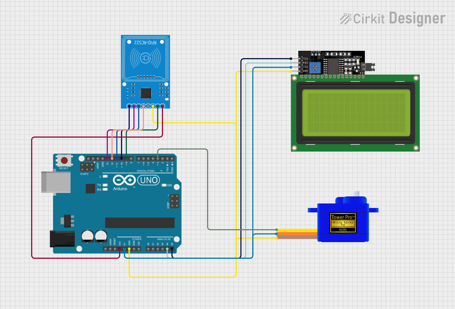
This circuit features an Arduino UNO microcontroller interfaced with an RFID-RC522 module for scanning RFID tags, a 20x4 LCD display with I2C communication for displaying scanned tag information, and a Servomotor SG90 for physical response upon tag detection. The Arduino manages the RFID reader to obtain tag data, controls the LCD to show the UID of the scanned tags, and signals the servo motor, potentially to actuate a mechanism like a lock. The provided code initializes the RFID reader and LCD, then continuously scans for RFID tags, displaying their UIDs on the LCD and sending the data over the serial connection.
This circuit integrates an Arduino Mega 2560 and an Arduino Nano to interface with an RFID-RC522 module. The Arduino Nano handles the RFID communication, while the Arduino Mega 2560 is connected to the Nano for additional processing or control tasks.
Read Range: Up to 6 meters (depending on antenna and tag)
Antenna Connections: U.FL and RP-SMA
Power Supply: 4.5V - 5.5V DC
Current Consumption: 80mA average / 1.5A peak (during transmit)
Supported Protocols: EPCglobal Gen 2 (ISO 18000-6C)
Pin Configuration and Descriptions
Pin Number
Name
Description
1
GND
Ground connection
2
VIN
Power supply input (4.5V - 5.5V DC)
3
EN
Enable pin (active high)
4
TX
UART transmit (to microcontroller RX)
5
RX
UART receive (from microcontroller TX)
6
SCLK
SPI clock
7
MISO
SPI Master In Slave Out
8
MOSI
SPI Master Out Slave In
9
SDA
I2C data
10
SCL
I2C clock
11
IRQ
Interrupt request (active high)
12
GPIO1
General purpose I/O (configurable)
Usage Instructions
How to Use the Component in a Circuit
Power Supply: Connect the VIN pin to a 4.5V - 5.5V DC power source and GND to the ground.
Interface Selection: By default, the module uses SPI. Connect SCLK, MISO, MOSI, and a GPIO pin for chip select (CS) to your microcontroller.
Antenna Connection: Attach a suitable UHF antenna to the U.FL or RP-SMA connector.
Enable the Module: Set the EN pin high to enable the module.
Communication: Establish communication with the module using the selected interface protocol (UART, I2C, or SPI).
Important Considerations and Best Practices
Ensure that the power supply is within the specified range and is capable of supplying the peak current required during transmit.
Use impedance-matched cables and antennas to maximize the read range and performance.
Place the module away from metal surfaces to avoid interference with the RFID signals.
Follow local regulations regarding the use of UHF RFID frequencies.
Troubleshooting and FAQs
Common Issues
Reader not powering up: Check the power supply connections and voltage levels.
No tags being read: Ensure the antenna is properly connected and the tags are within range and compatible with the UHF frequency.
Intermittent reading: Verify that the SPI or UART connections are secure and the microcontroller is correctly configured to communicate with the module.
Solutions and Tips for Troubleshooting
Double-check wiring and solder joints for any loose connections or shorts.
Use the provided library and example code to test basic functionality before integrating into a larger system.
Adjust the position and orientation of the antenna to improve tag detection.
FAQs
Q: Can the reader detect tags through materials?
A: Yes, but the effectiveness depends on the material. UHF RFID can penetrate materials like paper, plastic, and wood, but has difficulty with metal and liquids.
Q: How many tags can the reader read at once?
A: The M6E Nano can read multiple tags in its field; however, the exact number depends on the tags' orientations and environment.
Q: Is the reader compatible with all RFID tags?
A: It is compatible with tags that operate in the 860 to 960 MHz range and conform to the EPCglobal Gen 2 (ISO 18000-6C) standard.
Example Code for Arduino UNO
Below is a simple example code snippet for initializing the RFID reader with an Arduino UNO using the SPI interface. Ensure you have the appropriate library installed before uploading the code to the Arduino.
#include <SPI.h>
#include <RFID.h> // Make sure to include the correct library for the M6E Nano

// Define the pins
#define CS_PIN 10
#define RESET_PIN 9

RFID rfid(CS_PIN, RESET_PIN);

void setup() {
  Serial.begin(9600);
  SPI.begin();

  // Attempt to start the RFID reader
  if (rfid.begin() == false) {
    Serial.println("RFID reader not found. Please check wiring.");
    while (1); // Halt the program
  }
  Serial.println("RFID reader started successfully.");
}

void loop() {
  // Code to read RFID tags goes here
}
Remember to consult the library's documentation for detailed functions and additional examples to fully utilize the capabilities of the SparkFun Simultaneous RFID Reader - M6E Nano.


 Open Project in Cirkit Designer