How to Use Junction 3 IN 6 OUT: Examples, Pinouts, and Specs
Introduction
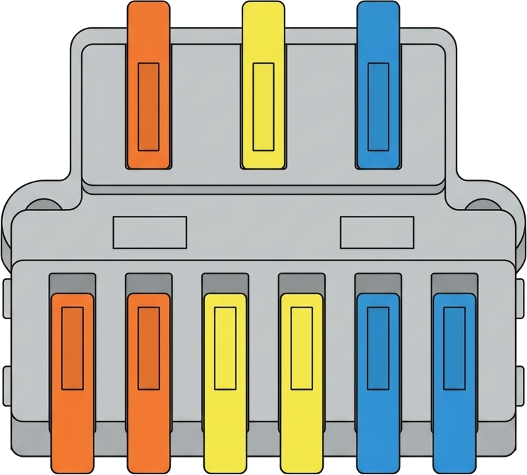
The Junction 3 IN 6 OUT is a versatile electronic component designed to facilitate the distribution of signals or power in a circuit. It features three input terminals and six output terminals, allowing users to connect multiple devices or subsystems efficiently. This component is commonly used in power distribution, signal splitting, and prototyping applications where multiple outputs are required from a limited number of inputs.
Explore Projects Built with Junction 3 IN 6 OUT

Explore Projects Built with Junction 3 IN 6 OUT
Common Applications and Use Cases
- Power distribution in low-voltage circuits
- Signal splitting for sensors or actuators
- Prototyping and breadboarding
- LED or small motor control circuits
- Expanding connections in Arduino or microcontroller projects
Technical Specifications
The following table outlines the key technical specifications of the Junction 3 IN 6 OUT component:
| Parameter | Value |
|---|---|
| Input Voltage Range | 3.3V to 24V |
| Maximum Current Rating | 5A per input terminal |
| Total Output Terminals | 6 |
| Input Terminals | 3 |
| Material | PCB with copper traces |
| Dimensions | 50mm x 30mm x 10mm |
| Mounting Type | Through-hole or screw mount |
Pin Configuration and Descriptions
The Junction 3 IN 6 OUT has the following pin configuration:
| Pin | Type | Description |
|---|---|---|
| IN1 | Input | First input terminal for power or signal |
| IN2 | Input | Second input terminal for power or signal |
| IN3 | Input | Third input terminal for power or signal |
| OUT1 | Output | First output terminal connected to IN1 |
| OUT2 | Output | Second output terminal connected to IN1 |
| OUT3 | Output | First output terminal connected to IN2 |
| OUT4 | Output | Second output terminal connected to IN2 |
| OUT5 | Output | First output terminal connected to IN3 |
| OUT6 | Output | Second output terminal connected to IN3 |
Usage Instructions
How to Use the Component in a Circuit
- Connect Inputs: Attach the input signals or power sources to the IN1, IN2, and IN3 terminals. Ensure the voltage and current ratings are within the specified range.
- Connect Outputs: Connect the devices or subsystems to the OUT1 through OUT6 terminals. Each pair of outputs corresponds to one input terminal.
- Secure Connections: Use screw terminals or solder the wires to ensure a reliable connection.
- Power On: Once all connections are secure, power on the circuit and verify the distribution of signals or power.
Important Considerations and Best Practices
- Avoid Overloading: Ensure the total current drawn from each input terminal does not exceed 5A.
- Voltage Compatibility: Verify that the connected devices are compatible with the input voltage.
- Signal Integrity: For signal distribution, use short wires to minimize noise and signal degradation.
- Heat Management: If operating near the maximum current rating, ensure proper ventilation to prevent overheating.
Example: Using with an Arduino UNO
The Junction 3 IN 6 OUT can be used to distribute power to multiple sensors or modules connected to an Arduino UNO. Below is an example of powering three LEDs using the junction:
Circuit Setup
- Connect the Arduino's 5V pin to the IN1 terminal.
- Connect the GND pin to the common ground of the circuit.
- Connect three LEDs to OUT1, OUT2, and OUT3, each with a 220-ohm resistor in series.
Arduino Code
// Example code to control three LEDs connected via the Junction 3 IN 6 OUT
const int led1 = 2; // Pin connected to LED 1
const int led2 = 3; // Pin connected to LED 2
const int led3 = 4; // Pin connected to LED 3

void setup() {
  pinMode(led1, OUTPUT); // Set LED 1 pin as output
  pinMode(led2, OUTPUT); // Set LED 2 pin as output
  pinMode(led3, OUTPUT); // Set LED 3 pin as output
}

void loop() {
  digitalWrite(led1, HIGH); // Turn on LED 1
  delay(500);               // Wait for 500ms
  digitalWrite(led1, LOW);  // Turn off LED 1
  digitalWrite(led2, HIGH); // Turn on LED 2
  delay(500);               // Wait for 500ms
  digitalWrite(led2, LOW);  // Turn off LED 2
  digitalWrite(led3, HIGH); // Turn on LED 3
  delay(500);               // Wait for 500ms
  digitalWrite(led3, LOW);  // Turn off LED 3
}
Troubleshooting and FAQs
Common Issues Users Might Face
No Output Signal or Power:
- Cause: Loose or improper connections.
- Solution: Check all connections and ensure wires are securely attached.
Overheating:
- Cause: Exceeding the maximum current rating.
- Solution: Reduce the load or distribute the current across multiple inputs.
Signal Degradation:
- Cause: Long wires or high-frequency signals.
- Solution: Use shorter wires and shielded cables for high-frequency signals.
Uneven Power Distribution:
- Cause: Mismatched loads on output terminals.
- Solution: Balance the load across outputs or use separate inputs for high-power devices.
FAQs
Q: Can I use this component for AC signals?
A: The Junction 3 IN 6 OUT is primarily designed for DC circuits. For AC applications, ensure the voltage and current ratings are not exceeded and consult the manufacturer.
Q: Can I connect all outputs to a single device?
A: Yes, but ensure the total current does not exceed the input terminal's maximum rating.
Q: Is this component suitable for high-frequency signals?
A: It can be used for low to moderate frequency signals. For high-frequency applications, consider using a dedicated signal splitter with impedance matching.
Q: Can I use fewer than three inputs?
A: Yes, unused input terminals can be left unconnected without affecting the performance of the other inputs and outputs.