
How to Use MH-CD42 Charge/Discharge(boost)/Battery: Examples, Pinouts, and Specs
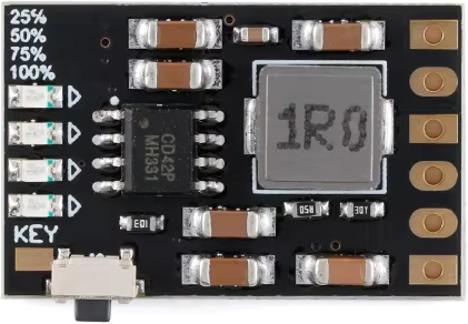
 Design with MH-CD42 Charge/Discharge(boost)/Battery in Cirkit Designer
Introduction
The MH-CD42 is a versatile charge/discharge controller designed for efficient battery management. It is capable of boosting voltage levels during discharge, ensuring stable and reliable power delivery to connected devices. Additionally, it regulates the charging process to optimize battery life and performance, making it an essential component for portable power systems, DIY electronics, and renewable energy projects.
Explore Projects Built with MH-CD42 Charge/Discharge(boost)/Battery
 Open Project in Cirkit Designer
 Open Project in Cirkit Designer
 Open Project in Cirkit Designer
 Open Project in Cirkit Designer
Explore Projects Built with MH-CD42 Charge/Discharge(boost)/Battery
Open Project in Cirkit DesignerOpen Project in Cirkit DesignerOpen Project in Cirkit DesignerOpen Project in Cirkit DesignerCommon Applications and Use Cases
- Power banks and portable chargers
- DIY battery-powered projects
- Solar-powered systems
- Battery backup systems
- Voltage regulation for low-power devices
Technical Specifications
The MH-CD42 is designed to handle a wide range of input and output conditions, making it suitable for various battery types and applications. Below are the key technical details:
| Parameter | Value |
|---|---|
| Input Voltage Range | 5V to 15V |
| Output Voltage Range | 5V to 12V (adjustable) |
| Maximum Output Current | 2A |
| Charging Current | 1A (default) |
| Efficiency | Up to 92% |
| Battery Type Supported | Lithium-ion, Lithium-polymer |
| Protection Features | Overcharge, Over-discharge, |
| Overcurrent, Short-circuit | |
| Dimensions | 36mm x 17mm x 6mm |
Pin Configuration and Descriptions
The MH-CD42 module has several key pins and connectors for input, output, and battery connections. Below is the pin configuration:
| Pin/Connector | Description |
|---|---|
| VIN+ | Positive input voltage terminal (5V to 15V). Connect to the power source. |
| VIN- | Negative input voltage terminal. Connect to the ground of the power source. |
| BAT+ | Positive terminal for the battery connection. |
| BAT- | Negative terminal for the battery connection. |
| OUT+ | Positive output voltage terminal. Connect to the load. |
| OUT- | Negative output voltage terminal. Connect to the ground of the load. |
| Adjustment Potentiometer | Used to adjust the output voltage (5V to 12V). |
Usage Instructions
How to Use the MH-CD42 in a Circuit
Connect the Power Source:
- Attach the positive terminal of your power source to the
VIN+pin. - Connect the negative terminal of your power source to the
VIN-pin. - Ensure the input voltage is within the range of 5V to 15V.
- Attach the positive terminal of your power source to the
Connect the Battery:
- Connect the positive terminal of the battery to the
BAT+pin. - Connect the negative terminal of the battery to the
BAT-pin. - Ensure the battery is compatible (e.g., Lithium-ion or Lithium-polymer).
- Connect the positive terminal of the battery to the
Connect the Load:
- Attach the positive terminal of your load to the
OUT+pin. - Connect the negative terminal of your load to the
OUT-pin.
- Attach the positive terminal of your load to the
Adjust the Output Voltage:
- Use the onboard potentiometer to set the desired output voltage (5V to 12V).
- Turn the potentiometer clockwise to increase the voltage and counterclockwise to decrease it.
Power On the Circuit:
- Once all connections are secure, power on the circuit.
- The module will regulate the charging and discharging process automatically.
Important Considerations and Best Practices
- Heat Dissipation: The module may heat up during operation, especially at high currents. Ensure proper ventilation or use a heatsink if necessary.
- Battery Protection: While the MH-CD42 includes built-in protection features, always use batteries with integrated protection circuits for added safety.
- Voltage Adjustment: Use a multimeter to measure the output voltage while adjusting the potentiometer to avoid overvoltage damage to your load.
- Polarity: Double-check all connections to ensure correct polarity. Reversing the polarity can damage the module.
Example: Using the MH-CD42 with an Arduino UNO
The MH-CD42 can be used to power an Arduino UNO by providing a stable 5V output. Below is an example setup:
- Set the output voltage of the MH-CD42 to 5V using the potentiometer.
- Connect the
OUT+pin to the Arduino's 5V pin. - Connect the
OUT-pin to the Arduino's GND pin. - Power the MH-CD42 using a battery or an external power source.
Here is a simple Arduino code to blink an LED while powered by the MH-CD42:
// Simple LED Blink Example
// This code blinks an LED connected to pin 13 of the Arduino UNO.
// Ensure the MH-CD42 is providing a stable 5V to the Arduino.

void setup() {
  pinMode(13, OUTPUT); // Set pin 13 as an output pin
}

void loop() {
  digitalWrite(13, HIGH); // Turn the LED on
  delay(1000);            // Wait for 1 second
  digitalWrite(13, LOW);  // Turn the LED off
  delay(1000);            // Wait for 1 second
}
Troubleshooting and FAQs
Common Issues and Solutions
No Output Voltage:
- Cause: Incorrect connections or insufficient input voltage.
- Solution: Verify all connections and ensure the input voltage is within the 5V to 15V range.
Overheating:
- Cause: High current draw or poor ventilation.
- Solution: Reduce the load current or improve ventilation around the module.
Battery Not Charging:
- Cause: Incorrect battery connection or incompatible battery type.
- Solution: Check the battery connections and ensure the battery is Lithium-ion or Lithium-polymer.
Output Voltage Fluctuations:
- Cause: Loose connections or unstable input voltage.
- Solution: Secure all connections and use a stable power source.
FAQs
Can the MH-CD42 charge multiple batteries in series?
No, the MH-CD42 is designed for single-cell Lithium-ion or Lithium-polymer batteries. For multiple cells, use a dedicated battery management system (BMS).What is the maximum load the MH-CD42 can handle?
The module can handle a maximum output current of 2A. Exceeding this limit may damage the module.Can I use the MH-CD42 with a solar panel?
Yes, as long as the solar panel's output voltage is within the 5V to 15V range.How do I know if the battery is fully charged?
The MH-CD42 typically includes an onboard LED indicator. Refer to the module's datasheet for specific LED behavior during charging.