How to Use 9-0-9 transformer: Examples, Pinouts, and Specs

Introduction
A 9-0-9 transformer is a type of step-down transformer designed to convert high AC voltage (typically from the mains) into two lower AC voltages of 9 volts each, with a center tap at 0 volts. The center tap allows for the creation of a dual voltage supply, which is essential in many electronic circuits. This transformer is widely used in power supply circuits, audio amplifiers, and other applications requiring dual voltage outputs.
Explore Projects Built with 9-0-9 transformer
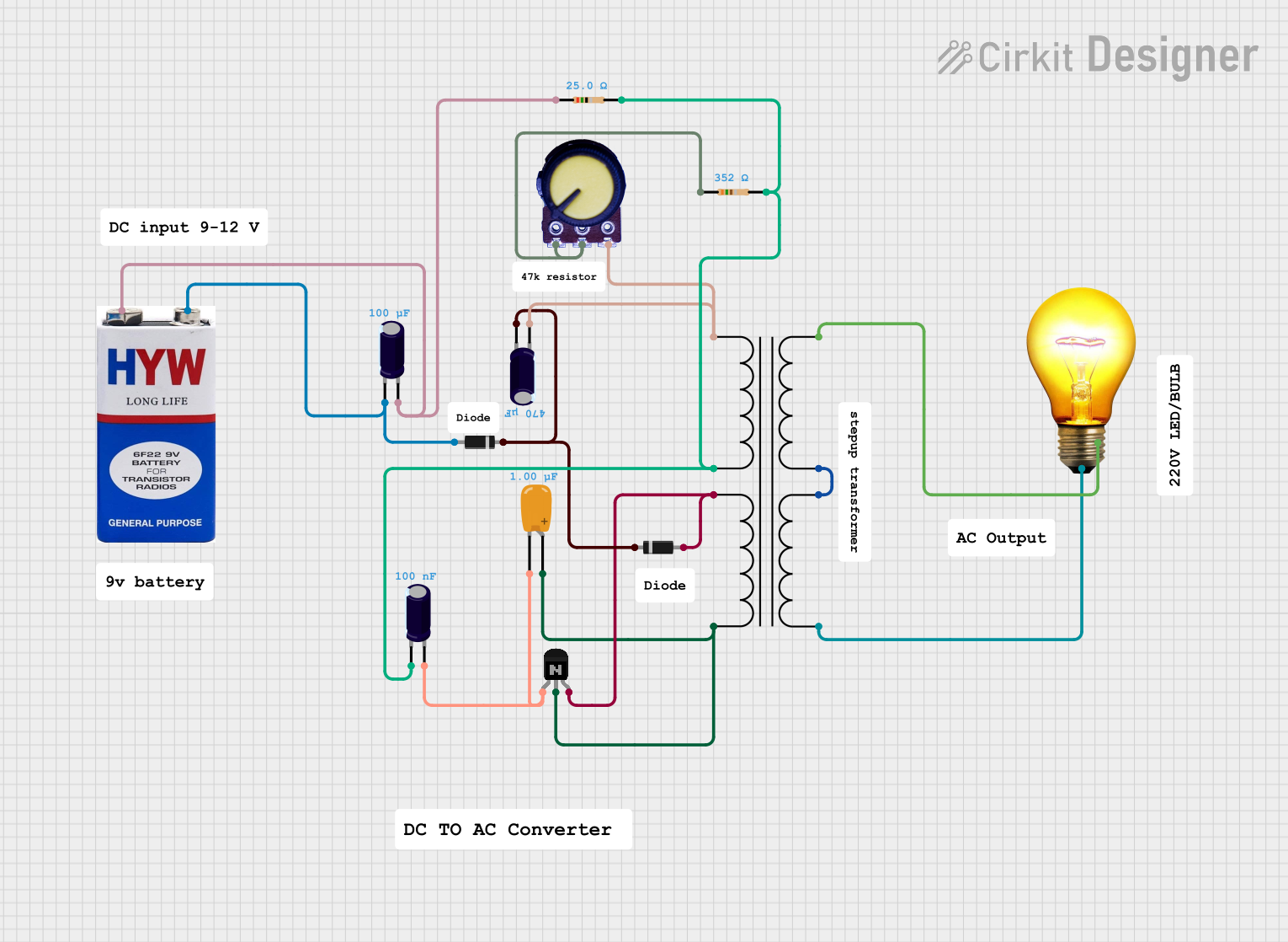

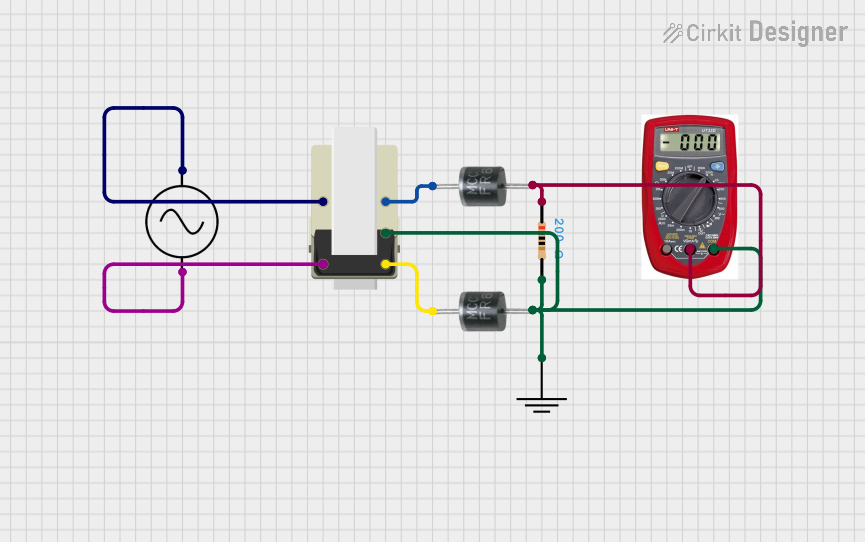
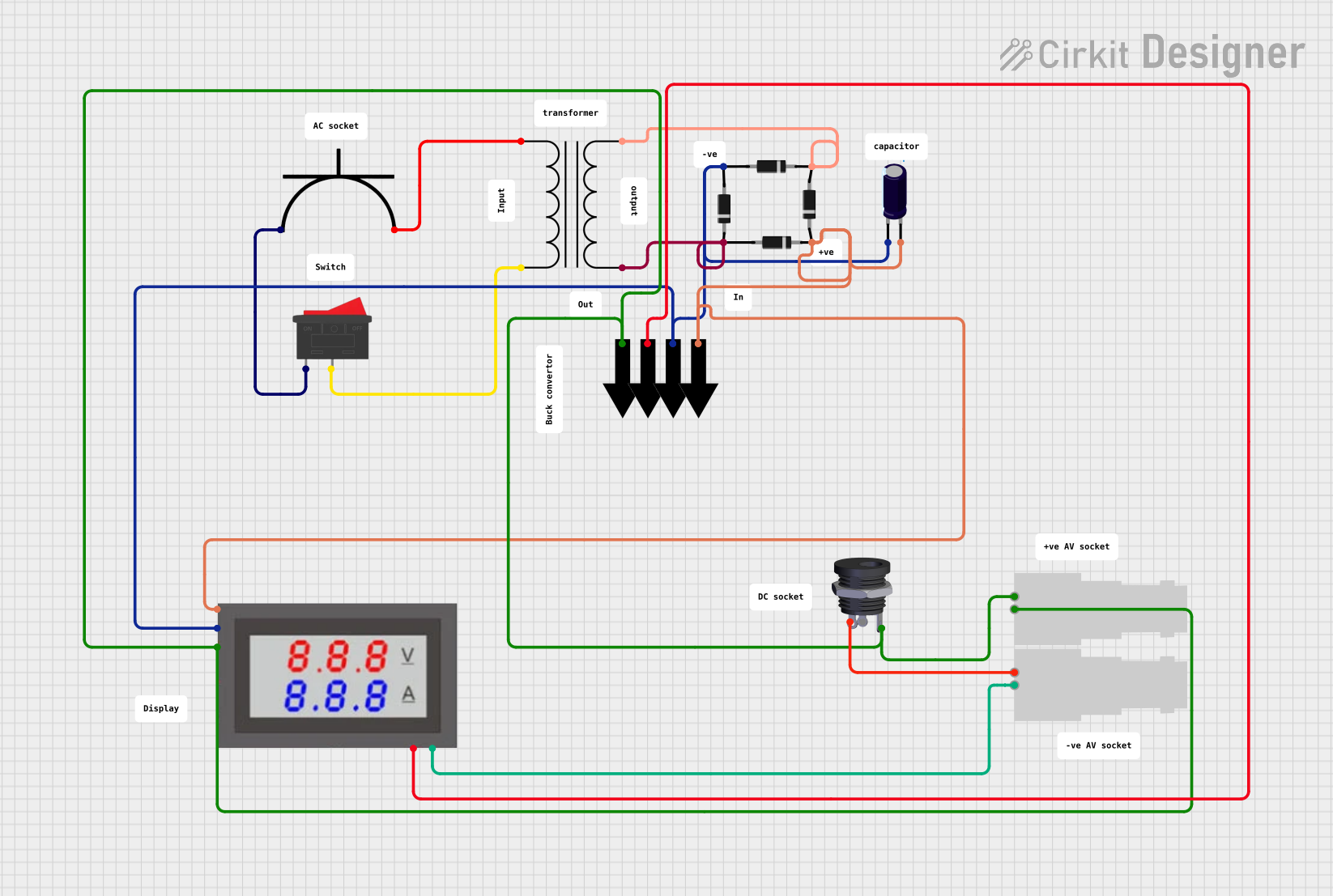
Explore Projects Built with 9-0-9 transformer
Common Applications and Use Cases
- Power supply circuits for converting AC mains voltage to lower AC voltages.
- Rectifier circuits for generating dual-polarity DC voltages.
- Audio amplifier circuits requiring dual voltage supplies.
- Low-power electronic devices and DIY projects.
Technical Specifications
Below are the key technical details of a typical 9-0-9 transformer:
| Parameter | Value |
|---|---|
| Input Voltage (Primary) | 220V AC or 110V AC (depending on model) |
| Output Voltage (Secondary) | 9V-0-9V AC |
| Frequency | 50Hz / 60Hz |
| Power Rating | Typically 12VA to 24VA |
| Current Rating | 1A to 2A (varies by model) |
| Winding Configuration | Center-tapped secondary winding |
| Insulation Class | Class B or Class F |
Pin Configuration and Descriptions
The 9-0-9 transformer typically has six terminals: three on the primary side and three on the secondary side. The table below describes the pin configuration:
Primary Side (Input)
| Pin | Description |
|---|---|
| P1 | Primary winding terminal 1 (AC input) |
| P2 | Primary winding terminal 2 (AC input) |
| P3 | Optional tap for dual input voltage (e.g., 110V/220V) |
Secondary Side (Output)
| Pin | Description |
|---|---|
| S1 | Secondary winding terminal 1 (9V AC output) |
| S2 | Center tap (0V reference) |
| S3 | Secondary winding terminal 2 (9V AC output) |
Usage Instructions
How to Use the 9-0-9 Transformer in a Circuit
Connect the Primary Side:
- Identify the primary winding terminals (P1 and P2). If your transformer supports dual input voltages (e.g., 110V/220V), ensure you connect the correct terminals based on your mains voltage.
- Connect the primary winding to the AC mains supply. Use proper insulation and safety precautions when handling mains voltage.
Connect the Secondary Side:
- Identify the secondary winding terminals (S1, S2, and S3). S1 and S3 provide 9V AC each, while S2 is the center tap (0V).
- For a dual-polarity output, connect S1 and S3 to a rectifier circuit, and use S2 as the ground reference.
- For a single 9V AC output, use either S1 or S3 with S2 as the ground.
Rectification and Filtering:
- To convert the AC output to DC, use a bridge rectifier circuit followed by a capacitor filter. This will provide a smooth DC voltage for powering electronic circuits.
Important Considerations and Best Practices
- Power Rating: Ensure the transformer’s power rating (VA) matches the load requirements of your circuit.
- Heat Dissipation: Transformers can heat up during operation. Provide adequate ventilation or a heat sink if necessary.
- Safety: Always handle the primary side with care, as it is connected to high-voltage AC mains. Use proper insulation and avoid direct contact.
- Fuse Protection: Use a fuse on the primary side to protect the transformer and circuit from overcurrent conditions.
Example: Using a 9-0-9 Transformer with an Arduino UNO
To power an Arduino UNO using a 9-0-9 transformer, you will need a rectifier circuit and a voltage regulator (e.g., 7805 for 5V output). Below is an example circuit and Arduino code:
Circuit Steps:
- Connect the secondary terminals (S1 and S3) to a bridge rectifier.
- Connect the rectifier output to a capacitor filter (e.g., 1000µF).
- Use a 7805 voltage regulator to step down the rectified voltage to 5V DC.
- Connect the 5V DC output to the Arduino UNO’s 5V and GND pins.
Arduino Code:
// Example code to blink an LED using Arduino UNO powered by a 9-0-9 transformer
// Ensure the transformer is connected to a rectifier and voltage regulator
// to provide a stable 5V DC supply to the Arduino.

const int ledPin = 13; // Pin connected to the onboard LED

void setup() {
  pinMode(ledPin, OUTPUT); // Set the LED pin as an output
}

void loop() {
  digitalWrite(ledPin, HIGH); // Turn the LED on
  delay(1000);               // Wait for 1 second
  digitalWrite(ledPin, LOW);  // Turn the LED off
  delay(1000);               // Wait for 1 second
}
Troubleshooting and FAQs
Common Issues and Solutions
Transformer Overheating:
- Cause: Overloading the transformer beyond its power rating.
- Solution: Reduce the load or use a transformer with a higher power rating.
No Output Voltage:
- Cause: Incorrect wiring or a blown fuse.
- Solution: Double-check the connections and replace the fuse if necessary.
Voltage Drop Under Load:
- Cause: Load current exceeds the transformer’s current rating.
- Solution: Use a transformer with a higher current rating.
Humming Noise:
- Cause: Loose laminations or improper mounting.
- Solution: Tighten the mounting screws and ensure the transformer is securely fixed.
FAQs
Q1: Can I use a 9-0-9 transformer to power a 12V device?
A1: No, the 9-0-9 transformer provides a maximum of 9V AC per winding. After rectification, the DC voltage will be approximately 12.7V (9V × √2). However, this may not be sufficient for devices requiring a stable 12V DC supply.
Q2: What is the purpose of the center tap?
A2: The center tap (0V) allows for the creation of a dual-polarity power supply (e.g., +9V and -9V), which is essential for certain circuits like audio amplifiers.
Q3: Can I use the transformer without a rectifier?
A3: Yes, but the output will remain AC. For DC-powered devices, a rectifier and filter circuit are required.
Q4: How do I calculate the transformer’s power rating?
A4: Multiply the output voltage (9V) by the current rating (e.g., 1A) and double it for both windings. For example, a 9-0-9 transformer with a 1A rating has a power rating of 18VA.