
How to Use IRF520 MOSFET Driver Module: Examples, Pinouts, and Specs
 Design with IRF520 MOSFET Driver Module in Cirkit Designer
Introduction
The IRF520 MOSFET Driver Module is a versatile electronic component designed to control high-power devices using low-power signals. It leverages the IRF520 N-channel MOSFET, which is known for its efficiency in switching and amplification. This module is commonly used in applications such as motor control, LED dimming, and driving high-current loads in automation systems. Its compact design and ease of use make it a popular choice for hobbyists and professionals alike.
Explore Projects Built with IRF520 MOSFET Driver Module
 Open Project in Cirkit Designer
 Open Project in Cirkit Designer
 Open Project in Cirkit Designer
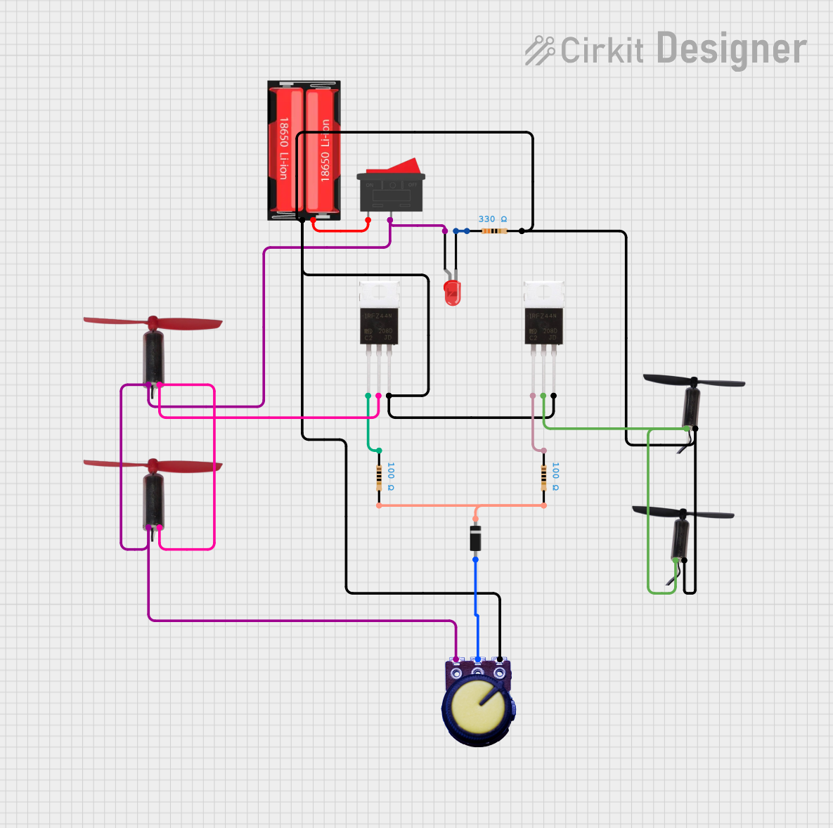 Open Project in Cirkit Designer
Explore Projects Built with IRF520 MOSFET Driver Module
Open Project in Cirkit DesignerOpen Project in Cirkit DesignerOpen Project in Cirkit DesignerOpen Project in Cirkit DesignerCommon Applications:
- Driving DC motors
- Controlling high-power LEDs
- Switching solenoids and relays
- General-purpose high-current load control
Technical Specifications
Below are the key technical details of the IRF520 MOSFET Driver Module:
| Parameter | Value |
|---|---|
| Operating Voltage | 3.3V to 5V |
| Maximum Drain-Source Voltage (VDS) | 100V |
| Maximum Continuous Drain Current (ID) | 9.2A |
| Gate Threshold Voltage (VGS(th)) | 2.0V to 4.0V |
| On-Resistance (RDS(on)) | 0.27Ω (at VGS = 10V) |
| Module Dimensions | ~33mm x 24mm x 12mm |
| Weight | ~5g |
Pin Configuration and Descriptions
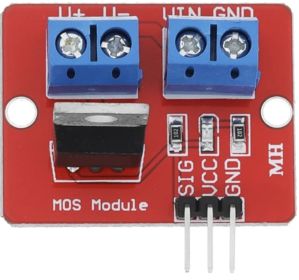
The IRF520 MOSFET Driver Module has a simple pinout, as shown below:
| Pin | Label | Description |
|---|---|---|
| 1 | VCC | Power input for the module (3.3V to 5V). |
| 2 | GND | Ground connection. |
| 3 | SIG | Signal input to control the MOSFET (PWM or digital signal). |
| 4 | V+ | Positive terminal for the external load (e.g., motor, LED). |
| 5 | OUT | Output terminal connected to the drain of the MOSFET (connect to the load). |
Usage Instructions
How to Use the IRF520 MOSFET Driver Module in a Circuit
- Power the Module: Connect the
VCCpin to a 3.3V or 5V power source and theGNDpin to the ground of your circuit. - Connect the Load: Attach the positive terminal of your load (e.g., motor or LED) to the
V+pin. Connect the negative terminal of the load to theOUTpin. - Control Signal: Provide a PWM or digital signal to the
SIGpin to control the MOSFET. A high signal turns the MOSFET on, allowing current to flow through the load. - Power Source for the Load: Ensure that the external power source for the load is connected to the
V+pin and shares a common ground with the module.
Important Considerations and Best Practices
- Voltage Compatibility: Ensure the control signal voltage matches the module's operating voltage (3.3V or 5V).
- Heat Dissipation: For high-current loads, consider adding a heatsink to the MOSFET to prevent overheating.
- Load Protection: Use a flyback diode across inductive loads (e.g., motors) to protect the MOSFET from voltage spikes.
- Signal Quality: For PWM control, ensure the signal frequency is appropriate for your application (e.g., 1kHz to 10kHz for motor control).
Example: Using the IRF520 Module with Arduino UNO
Below is an example of how to use the IRF520 MOSFET Driver Module to control an LED with an Arduino UNO:
// Define the pin connected to the SIG pin of the IRF520 module
const int mosfetPin = 9;

void setup() {
  pinMode(mosfetPin, OUTPUT); // Set the MOSFET control pin as an output
}

void loop() {
  // Gradually increase brightness
  for (int brightness = 0; brightness <= 255; brightness++) {
    analogWrite(mosfetPin, brightness); // Send PWM signal to control brightness
    delay(10); // Small delay for smooth transition
  }

  // Gradually decrease brightness
  for (int brightness = 255; brightness >= 0; brightness--) {
    analogWrite(mosfetPin, brightness); // Send PWM signal to control brightness
    delay(10); // Small delay for smooth transition
  }
}
Notes:
- Replace the LED with any other load (e.g., motor) as needed, ensuring the load's current and voltage are within the module's specifications.
- Use an external power source for high-power loads, and connect its ground to the Arduino's ground.
Troubleshooting and FAQs
Common Issues and Solutions
The load does not turn on:
- Ensure the
SIGpin is receiving a valid control signal (PWM or digital HIGH). - Verify that the external power source is properly connected to the
V+pin. - Check the load's connections and ensure it is functional.
- Ensure the
MOSFET overheating:
- Ensure the load's current does not exceed the MOSFET's maximum rating (9.2A).
- Add a heatsink to the MOSFET for better heat dissipation.
- Use a lower PWM duty cycle to reduce power dissipation.
PWM signal not working as expected:
- Verify the PWM frequency and duty cycle are appropriate for your application.
- Check the Arduino code for errors and ensure the correct pin is used for PWM output.
Voltage spikes damaging the MOSFET:
- For inductive loads, always use a flyback diode across the load to suppress voltage spikes.
FAQs
Q: Can I use the IRF520 module with a 12V motor?
A: Yes, the IRF520 module can handle up to 100V on the drain-source voltage. Ensure the motor's current does not exceed 9.2A.
Q: Is the IRF520 module compatible with 3.3V logic?
A: While the module can operate with 3.3V signals, the MOSFET may not fully turn on at lower gate voltages. For optimal performance, use a 5V control signal.
Q: Can I control multiple loads with one module?
A: No, the IRF520 module is designed to control a single load. Use separate modules for multiple loads.
Q: Do I need a heatsink for low-power applications?
A: For low-power loads (e.g., LEDs), a heatsink is not necessary. However, for high-current loads, a heatsink is recommended.
This concludes the documentation for the IRF520 MOSFET Driver Module.