
How to Use LCD 12C : Examples, Pinouts, and Specs
 Design with LCD 12C in Cirkit Designer
Introduction
The LCD I2C module is a Liquid Crystal Display (LCD) that utilizes the I2C (Inter-Integrated Circuit) communication protocol for simplified interfacing with microcontrollers. This module is widely used for displaying text, numbers, and simple graphics in embedded systems. Its compact design and reduced pin usage make it an ideal choice for projects where GPIO pins are limited.
Explore Projects Built with LCD 12C
 Open Project in Cirkit Designer
 Open Project in Cirkit Designer
 Open Project in Cirkit Designer
 Open Project in Cirkit Designer
Explore Projects Built with LCD 12C
Open Project in Cirkit DesignerOpen Project in Cirkit DesignerOpen Project in Cirkit DesignerOpen Project in Cirkit DesignerCommon Applications and Use Cases
- Displaying sensor data in IoT projects
- User interfaces for embedded systems
- Menu systems for devices
- Educational and prototyping purposes
- Home automation displays
Technical Specifications
Key Technical Details
- Display Type: 16x2 or 20x4 character LCD (varies by model)
- Communication Protocol: I2C
- Operating Voltage: 5V DC
- Backlight: LED with adjustable brightness
- I2C Address: Typically 0x27 or 0x3F (configurable)
- Current Consumption: ~20mA (with backlight on)
- Contrast Adjustment: Via onboard potentiometer
- Operating Temperature: -20°C to 70°C
Pin Configuration and Descriptions
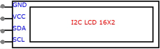
The LCD I2C module has a 4-pin interface for I2C communication. Below is the pinout:
| Pin Name | Description |
|---|---|
| VCC | Power supply (5V DC) |
| GND | Ground |
| SDA | Serial Data Line for I2C communication |
| SCL | Serial Clock Line for I2C communication |
Usage Instructions
How to Use the LCD I2C in a Circuit
Connect the Module:
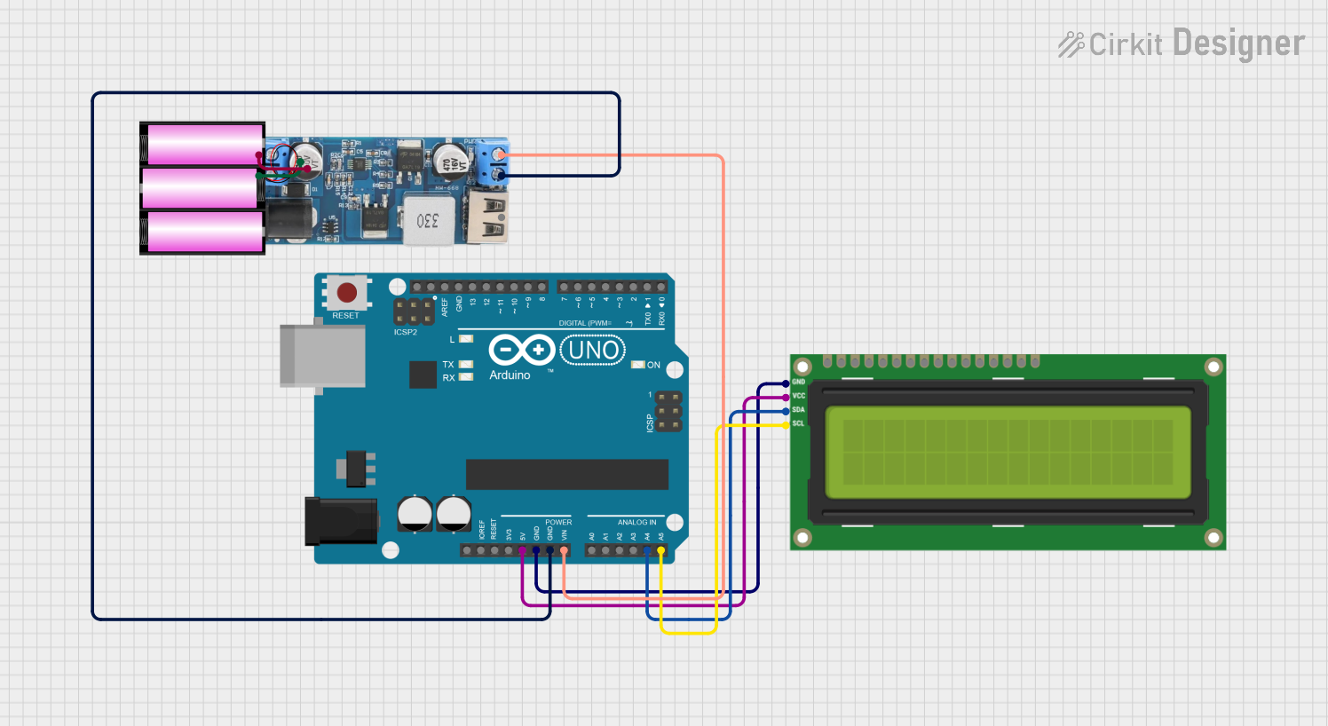
- Connect the
VCCpin to the 5V pin of your microcontroller. - Connect the
GNDpin to the ground (GND) of your microcontroller. - Connect the
SDApin to the I2C data line (e.g., A4 on Arduino UNO). - Connect the
SCLpin to the I2C clock line (e.g., A5 on Arduino UNO).
- Connect the
Install Required Libraries:
- Use the
LiquidCrystal_I2Clibrary for Arduino. Install it via the Arduino IDE Library Manager:- Go to Sketch > Include Library > Manage Libraries.
- Search for
LiquidCrystal_I2Cand install the library by Frank de Brabander.
- Use the
Write and Upload Code:
- Use the example code below to display text on the LCD.
Example Code for Arduino UNO
#include <Wire.h>                // Include the Wire library for I2C communication
#include <LiquidCrystal_I2C.h>   // Include the LiquidCrystal_I2C library

// Initialize the LCD with I2C address 0x27 and a 16x2 display
LiquidCrystal_I2C lcd(0x27, 16, 2);

void setup() {
  lcd.begin();                   // Initialize the LCD
  lcd.backlight();               // Turn on the backlight
  lcd.setCursor(0, 0);           // Set cursor to the first row, first column
  lcd.print("Hello, World!");    // Print text on the first row
  lcd.setCursor(0, 1);           // Set cursor to the second row, first column
  lcd.print("LCD I2C Module");   // Print text on the second row
}

void loop() {
  // No actions in the loop for this example
}
Important Considerations and Best Practices
- I2C Address: Ensure the correct I2C address is used in your code. If the module does not respond, use an I2C scanner sketch to detect the address.
- Contrast Adjustment: Use the onboard potentiometer to adjust the contrast of the display.
- Power Supply: Ensure a stable 5V power supply to avoid flickering or malfunctioning.
- Pull-Up Resistors: Some I2C modules include onboard pull-up resistors for SDA and SCL lines. If not, external pull-up resistors (4.7kΩ to 10kΩ) may be required.
Troubleshooting and FAQs
Common Issues and Solutions
No Display or Backlight:
- Verify the power connections (VCC and GND).
- Check if the backlight is enabled in the code (
lcd.backlight()).
Incorrect or No Text Displayed:
- Ensure the correct I2C address is used in the code.
- Adjust the contrast using the potentiometer.
Flickering or Unstable Display:
- Check for loose connections.
- Ensure the power supply is stable and sufficient.
I2C Address Not Detected:
- Use an I2C scanner sketch to detect the module's address.
- Verify the SDA and SCL connections.
FAQs
Q: Can I use the LCD I2C module with a 3.3V microcontroller?
A: Yes, but ensure the module supports 3.3V logic levels or use a level shifter.
Q: How do I display custom characters?
A: Use the createChar() function in the LiquidCrystal_I2C library to define and display custom characters.
Q: Can I connect multiple I2C devices to the same microcontroller?
A: Yes, as long as each device has a unique I2C address. Use an I2C multiplexer if address conflicts occur.
Q: What is the maximum cable length for I2C communication?
A: The maximum length depends on the pull-up resistor values and communication speed, but typically it is limited to 1 meter for reliable operation.
By following this documentation, you can effectively integrate and troubleshoot the LCD I2C module in your projects.