
How to Use OV7670 CameraChip: Examples, Pinouts, and Specs
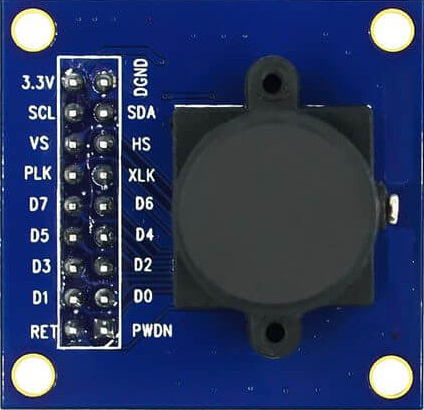
 Design with OV7670 CameraChip in Cirkit Designer
Introduction
The OV7670 CameraChip, manufactured by OmniVision (Part ID: OV7670), is a low-cost image sensor designed for capturing video and still images. It features a VGA resolution of 640x480 pixels and supports multiple output formats, making it a versatile choice for a wide range of applications. The OV7670 is widely used in embedded systems, robotics, and IoT devices for image processing tasks such as object detection, facial recognition, and video streaming.
Explore Projects Built with OV7670 CameraChip
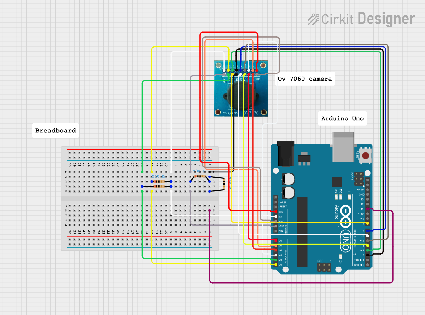
 Open Project in Cirkit Designer
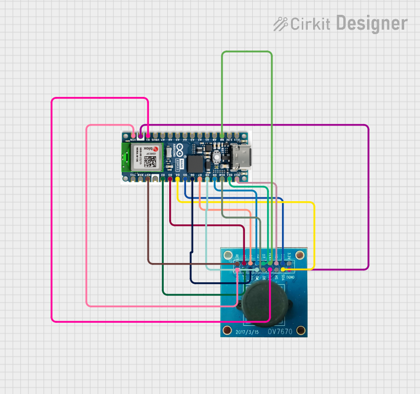
 Open Project in Cirkit Designer
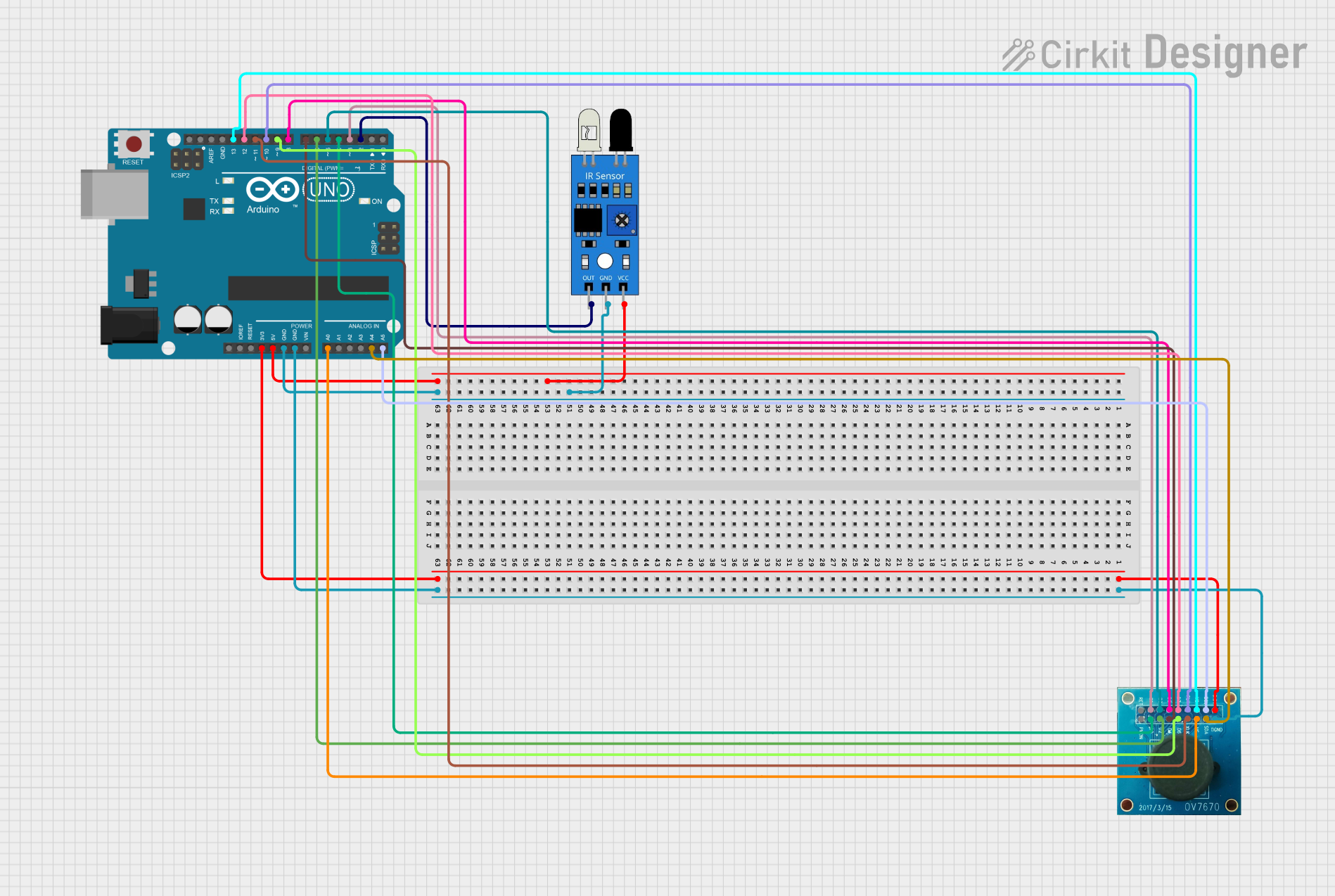
 Open Project in Cirkit Designer
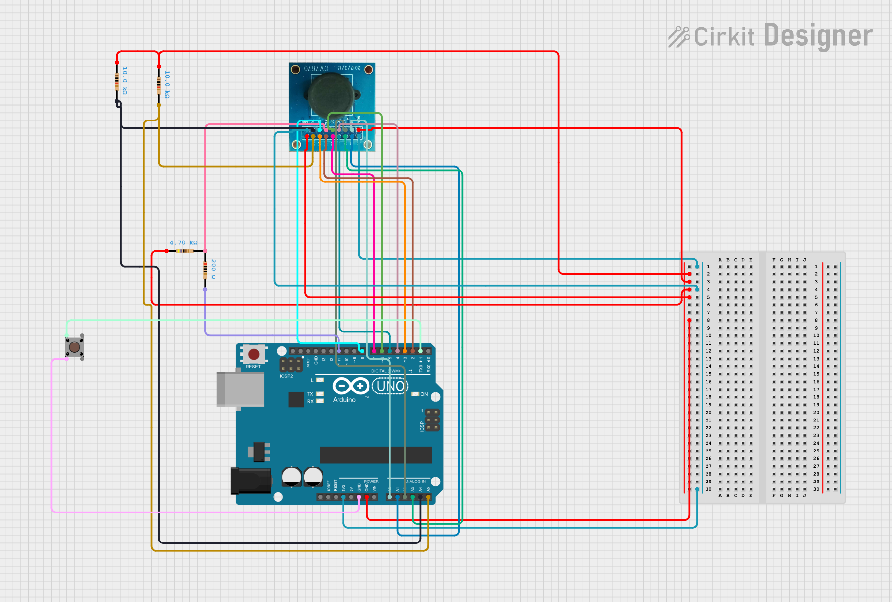
 Open Project in Cirkit Designer
Explore Projects Built with OV7670 CameraChip

 Open Project in Cirkit Designer
 Open Project in Cirkit Designer
 Open Project in Cirkit Designer
 Open Project in Cirkit Designer
Common Applications
- Embedded systems for image and video capture
- Robotics for vision-based navigation and object detection
- IoT devices for surveillance and monitoring
- Educational projects involving image processing
- Machine learning applications requiring visual data input
Technical Specifications
Key Technical Details
| Parameter | Value |
|---|---|
| Resolution | VGA (640x480 pixels) |
| Pixel Size | 3.6 µm x 3.6 µm |
| Maximum Frame Rate | 30 frames per second (fps) |
| Output Formats | YUV, RGB, GRB422, and more |
| Operating Voltage | 2.5V (analog), 1.8V (digital) |
| Power Consumption | ~60 mW |
| Operating Temperature | -30°C to +70°C |
| Lens Size | 1/6 inch |
| Field of View (FOV) | 25° to 60° (depending on lens) |
| Communication Interface | SCCB (Serial Camera Control Bus) |
Pin Configuration and Descriptions
The OV7670 CameraChip has 18 pins. Below is the pinout and description:
| Pin No. | Pin Name | Description |
|---|---|---|
| 1 | GND | Ground connection |
| 2 | VCC | Power supply (2.5V for analog, 1.8V for digital) |
| 3 | SCL | SCCB clock line for communication |
| 4 | SDA | SCCB data line for communication |
| 5 | VSYNC | Vertical synchronization signal |
| 6 | HREF | Horizontal reference signal |
| 7 | PCLK | Pixel clock output |
| 8 | XCLK | External clock input (typically 24 MHz) |
| 9 | D0 | Data bit 0 (LSB) |
| 10 | D1 | Data bit 1 |
| 11 | D2 | Data bit 2 |
| 12 | D3 | Data bit 3 |
| 13 | D4 | Data bit 4 |
| 14 | D5 | Data bit 5 |
| 15 | D6 | Data bit 6 |
| 16 | D7 | Data bit 7 (MSB) |
| 17 | RESET | Active-low reset signal |
| 18 | PWDN | Power-down mode (active high) |
Usage Instructions
How to Use the OV7670 in a Circuit
- Power Supply: Connect the VCC pin to a 2.5V analog power source and the digital logic to 1.8V. Ensure proper decoupling capacitors are used to stabilize the power supply.
- Clock Input: Provide a stable 24 MHz clock signal to the XCLK pin. This can be generated using an external oscillator or a microcontroller.
- Communication: Use the SCCB interface (SCL and SDA pins) to configure the camera's registers. This is similar to I2C communication.
- Data Output: The camera outputs image data through the D0-D7 pins, synchronized with the PCLK signal. Use the VSYNC and HREF signals to determine frame and line boundaries.
- Reset and Power-Down: Use the RESET and PWDN pins to control the camera's operational state.
Important Considerations
- Voltage Levels: Ensure the logic levels of your microcontroller match the OV7670's requirements (1.8V for digital signals).
- Clock Stability: A stable clock signal is critical for proper operation.
- Lens Adjustment: Depending on your application, you may need to adjust the lens focus manually.
- Noise Reduction: Use proper grounding and shielding to minimize noise in the image data.
Example: Connecting OV7670 to Arduino UNO
The Arduino UNO operates at 5V logic, so a level shifter is required to interface with the OV7670. Below is an example code snippet to initialize the OV7670 using the SCCB interface.
#include <Wire.h> // Include the Wire library for I2C communication

#define OV7670_ADDR 0x42 // OV7670 SCCB address (write mode)

void setup() {
  Wire.begin(); // Initialize I2C communication
  Serial.begin(9600); // Initialize serial communication for debugging

  // Reset the OV7670
  writeRegister(0x12, 0x80); // Reset register

  // Configure the OV7670 for VGA resolution and YUV output
  writeRegister(0x12, 0x00); // Set VGA mode
  writeRegister(0x11, 0x01); // Set clock prescaler
  writeRegister(0x0C, 0x04); // Enable YUV output

  Serial.println("OV7670 initialized.");
}

void loop() {
  // Main loop can be used to process image data
}

// Function to write to OV7670 registers
void writeRegister(uint8_t reg, uint8_t value) {
  Wire.beginTransmission(OV7670_ADDR);
  Wire.write(reg); // Register address
  Wire.write(value); // Register value
  Wire.endTransmission();
}
Notes:
- Use a level shifter to convert the Arduino's 5V logic to 1.8V for the OV7670.
- The above code initializes the camera but does not handle image data processing. Additional libraries or hardware (e.g., an external memory buffer) may be required for full functionality.
Troubleshooting and FAQs
Common Issues
No Image Output:
- Ensure the XCLK signal is stable and within the required frequency range (24 MHz).
- Verify the SCCB communication and check if the camera registers are being configured correctly.
Distorted or Noisy Images:
- Check the power supply for noise or instability.
- Ensure proper grounding and shielding of the circuit.
Camera Not Responding:
- Verify the SCCB address (default is 0x42 for write and 0x43 for read).
- Check the RESET and PWDN pins to ensure the camera is not in a reset or power-down state.
Tips for Troubleshooting
- Use an oscilloscope to verify the clock and data signals.
- Double-check all connections, especially the power supply and communication lines.
- Refer to the OV7670 datasheet for detailed register descriptions and configuration options.
FAQs
Q: Can the OV7670 capture color images?
A: Yes, the OV7670 supports color image capture in formats such as RGB and YUV.
Q: What is the maximum frame rate of the OV7670?
A: The OV7670 can capture up to 30 frames per second at VGA resolution.
Q: Can the OV7670 be used with a Raspberry Pi?
A: Yes, but additional configuration and possibly a level shifter are required to interface with the Raspberry Pi's GPIO pins.
Q: Does the OV7670 support autofocus?
A: No, the OV7670 requires manual focus adjustment.