Cirkit Designer Logo
Cirkit Designer
Your all-in-one circuit design IDE
Home / 
Component Documentation

How to Use QTR-8A: Examples, Pinouts, and Specs

Image of QTR-8A
Cirkit Designer LogoDesign with QTR-8A in Cirkit Designer

Introduction

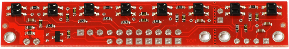
The QTR-8A, manufactured by Pololu, is an array of eight infrared (IR) emitter and detector pairs designed for line sensing and object detection. This versatile sensor module outputs analog signals corresponding to the reflectance detected by each sensor, making it ideal for robotics and automation applications. The QTR-8A is commonly used in line-following robots, edge detection systems, and object tracking.

Explore Projects Built with QTR-8A

Use Cirkit Designer to design, explore, and prototype these projects online. Some projects support real-time simulation. Click "Open Project" to start designing instantly!
Arduino Nano-Powered PID Line Following Robot with Reflectance Sensor Array and Dual Motor Driver
Image of Line following bot: A project utilizing QTR-8A in a practical application
This circuit is designed for an advanced line-following robot that uses a QTRX-HD-07RC Reflectance Sensor Array for line sensing and a Motor Driver 1A Dual TB6612FNG to control two DC Mini Metal Gear Motors. The Arduino Nano serves as the microcontroller, running a PID control algorithm to adjust the motor speeds for precise tracking. Power is supplied by a 5V battery for the logic and a 12V battery for the motor driver.
Cirkit Designer LogoOpen Project in Cirkit Designer
Adafruit MPU6050 and VL6180X Sensor Interface with Servo Control
Image of wire: A project utilizing QTR-8A in a practical application
This circuit features an Adafruit QT Py microcontroller interfaced with an Adafruit MPU6050 6-axis accelerometer/gyroscope and an Adafruit VL6180X Time of Flight (ToF) distance sensor, both connected via I2C communication. The QT Py also controls a Servomotor SG90, likely for physical actuation based on sensor inputs. The embedded code initializes the sensors, reads their data, and outputs the readings to a serial monitor, with the potential for motion control based on the sensor feedback.
Cirkit Designer LogoOpen Project in Cirkit Designer
Arduino Mega 2560 Battery-Powered Robotic Vehicle with Reflectance Sensor and Motor Control
Image of PID Line Following Robot (No ESP32 or US): A project utilizing QTR-8A in a practical application
This circuit is a motor control system powered by 18650 Li-ion batteries, featuring an Arduino Mega 2560 microcontroller that controls two gear motors with integrated encoders via a TB6612FNG motor driver. It also includes a QTRX-HD-07RC reflectance sensor array for line following, and power management components such as a lithium battery charging board, a step-up boost converter, and a buck converter to regulate voltage.
Cirkit Designer LogoOpen Project in Cirkit Designer
A-Star 32U4 Mini Controlled Servo with VL53L8CX Time-of-Flight Distance Sensing
Image of Servo con distance sensor: A project utilizing QTR-8A in a practical application
This circuit features an A-Star 32U4 Mini microcontroller connected to a VL53L8CX Time-of-Flight distance sensor and a servo motor. The microcontroller powers both the sensor and the servo, and it is configured to communicate with the sensor via I2C (using pins 2 and 3 for SDA and SCL, respectively) and to control the servo via a PWM signal on pin 10. The purpose of the circuit is likely to measure distances and respond with movements of the servo based on the sensor readings.
Cirkit Designer LogoOpen Project in Cirkit Designer

Explore Projects Built with QTR-8A

Use Cirkit Designer to design, explore, and prototype these projects online. Some projects support real-time simulation. Click "Open Project" to start designing instantly!
Image of Line following bot: A project utilizing QTR-8A in a practical application
Arduino Nano-Powered PID Line Following Robot with Reflectance Sensor Array and Dual Motor Driver
This circuit is designed for an advanced line-following robot that uses a QTRX-HD-07RC Reflectance Sensor Array for line sensing and a Motor Driver 1A Dual TB6612FNG to control two DC Mini Metal Gear Motors. The Arduino Nano serves as the microcontroller, running a PID control algorithm to adjust the motor speeds for precise tracking. Power is supplied by a 5V battery for the logic and a 12V battery for the motor driver.
Cirkit Designer LogoOpen Project in Cirkit Designer
Image of wire: A project utilizing QTR-8A in a practical application
Adafruit MPU6050 and VL6180X Sensor Interface with Servo Control
This circuit features an Adafruit QT Py microcontroller interfaced with an Adafruit MPU6050 6-axis accelerometer/gyroscope and an Adafruit VL6180X Time of Flight (ToF) distance sensor, both connected via I2C communication. The QT Py also controls a Servomotor SG90, likely for physical actuation based on sensor inputs. The embedded code initializes the sensors, reads their data, and outputs the readings to a serial monitor, with the potential for motion control based on the sensor feedback.
Cirkit Designer LogoOpen Project in Cirkit Designer
Image of PID Line Following Robot (No ESP32 or US): A project utilizing QTR-8A in a practical application
Arduino Mega 2560 Battery-Powered Robotic Vehicle with Reflectance Sensor and Motor Control
This circuit is a motor control system powered by 18650 Li-ion batteries, featuring an Arduino Mega 2560 microcontroller that controls two gear motors with integrated encoders via a TB6612FNG motor driver. It also includes a QTRX-HD-07RC reflectance sensor array for line following, and power management components such as a lithium battery charging board, a step-up boost converter, and a buck converter to regulate voltage.
Cirkit Designer LogoOpen Project in Cirkit Designer
Image of Servo con distance sensor: A project utilizing QTR-8A in a practical application
A-Star 32U4 Mini Controlled Servo with VL53L8CX Time-of-Flight Distance Sensing
This circuit features an A-Star 32U4 Mini microcontroller connected to a VL53L8CX Time-of-Flight distance sensor and a servo motor. The microcontroller powers both the sensor and the servo, and it is configured to communicate with the sensor via I2C (using pins 2 and 3 for SDA and SCL, respectively) and to control the servo via a PWM signal on pin 10. The purpose of the circuit is likely to measure distances and respond with movements of the servo based on the sensor readings.
Cirkit Designer LogoOpen Project in Cirkit Designer

Common Applications

  • Line-following robots
  • Edge detection in robotic navigation
  • Object detection and tracking
  • Industrial automation systems
  • Position sensing in conveyor belts

Technical Specifications

The QTR-8A sensor array is designed for ease of use and high performance. Below are its key technical details:

General Specifications

  • Operating Voltage: 3.3V to 5V
  • Current Consumption: ~100 mA (with all emitters on)
  • Output Type: Analog voltage (0V to Vcc)
  • Sensor Count: 8 IR emitter-detector pairs
  • Optimal Sensing Distance: 3 mm to 6 mm
  • Maximum Sensing Distance: ~25 mm (depending on surface reflectivity)
  • Dimensions: 76.2 mm × 12.7 mm × 3.2 mm
  • Weight: 3.09 g

Pin Configuration

The QTR-8A has a 10-pin header for easy interfacing. The table below describes each pin:

Pin Name Description
1 Vcc Power supply input (3.3V to 5V)
2 GND Ground connection
3 OUT1 Analog output for sensor 1
4 OUT2 Analog output for sensor 2
5 OUT3 Analog output for sensor 3
6 OUT4 Analog output for sensor 4
7 OUT5 Analog output for sensor 5
8 OUT6 Analog output for sensor 6
9 OUT7 Analog output for sensor 7
10 OUT8 Analog output for sensor 8

Additional Features

  • Emitter Control: The IR emitters can be turned on or off using a separate control pin (not included in the main header).
  • Adjustable Sensitivity: The output voltage varies based on the reflectivity of the surface, allowing for fine-tuned sensing.

Usage Instructions

The QTR-8A is straightforward to integrate into a circuit. Follow the steps below to use it effectively:

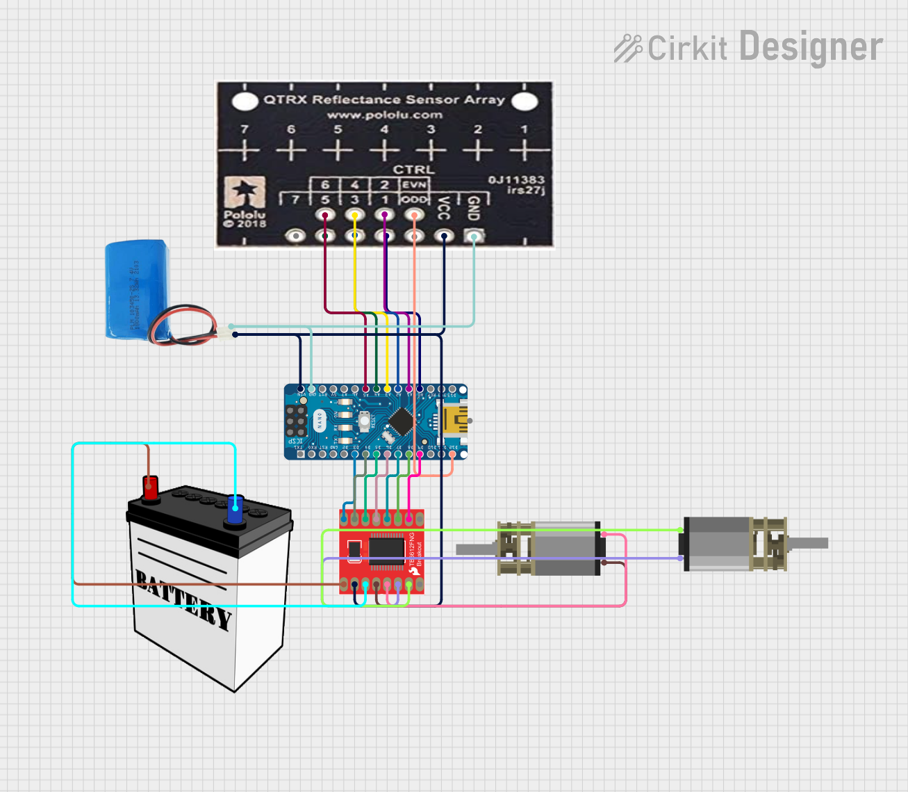
Connecting the QTR-8A

  1. Power Supply: Connect the Vcc pin to a 3.3V or 5V power source and the GND pin to ground.
  2. Analog Outputs: Connect the OUT1 to OUT8 pins to the analog input pins of your microcontroller (e.g., Arduino).
  3. Emitter Control (Optional): Use the emitter control pin to enable or disable the IR emitters programmatically.

Example Circuit with Arduino UNO

Below is an example of how to connect the QTR-8A to an Arduino UNO:

  • Connect the Vcc pin of the QTR-8A to the 5V pin on the Arduino.
  • Connect the GND pin of the QTR-8A to the GND pin on the Arduino.
  • Connect OUT1 to OUT8 to the Arduino's analog input pins (A0 to A7).

Sample Arduino Code

The following code reads the analog values from the QTR-8A and prints them to the Serial Monitor:

// Define the analog input pins connected to the QTR-8A
const int sensorPins[8] = {A0, A1, A2, A3, A4, A5, A6, A7};

void setup() {
  Serial.begin(9600); // Initialize serial communication at 9600 baud
}

void loop() {
  for (int i = 0; i < 8; i++) {
    int sensorValue = analogRead(sensorPins[i]); // Read analog value from each sensor
    Serial.print("Sensor ");
    Serial.print(i + 1);
    Serial.print(": ");
    Serial.print(sensorValue);
    Serial.print("\t"); // Add a tab space between sensor readings
  }
  Serial.println(); // Move to the next line after printing all sensor values
  delay(100); // Wait 100 ms before the next reading
}

Important Considerations

  • Surface Reflectivity: The sensor's output depends on the reflectivity of the surface. Darker surfaces (e.g., black lines) produce lower output voltages, while lighter surfaces (e.g., white backgrounds) produce higher voltages.
  • Emitter Control: To save power, you can disable the IR emitters when the sensor is not in use.
  • Distance from Surface: For optimal performance, maintain a distance of 3 mm to 6 mm between the sensor and the surface.

Troubleshooting and FAQs

Common Issues

  1. No Output or Incorrect Readings

    • Cause: Improper wiring or insufficient power supply.
    • Solution: Double-check all connections and ensure the power supply is within the specified range (3.3V to 5V).
  2. Inconsistent Sensor Readings

    • Cause: Uneven surface or incorrect sensor height.
    • Solution: Ensure the sensor array is parallel to the surface and within the optimal sensing distance (3 mm to 6 mm).
  3. High Power Consumption

    • Cause: All IR emitters are always on.
    • Solution: Use the emitter control pin to turn off the emitters when not in use.
  4. Sensors Not Detecting Black Lines

    • Cause: Low contrast between the line and the background.
    • Solution: Use a surface with higher contrast (e.g., black tape on a white background).

FAQs

Q: Can the QTR-8A be used with a 3.3V microcontroller?
A: Yes, the QTR-8A operates at 3.3V to 5V, making it compatible with 3.3V microcontrollers.

Q: How do I calibrate the sensor for my application?
A: You can calibrate the sensor by recording the maximum and minimum output values during operation and mapping the readings to a desired range.

Q: Can I use fewer than 8 sensors?
A: Yes, you can use only the required number of sensors by connecting the corresponding output pins to your microcontroller and leaving the others unconnected.

Q: What is the maximum sensing distance?
A: The maximum sensing distance is approximately 25 mm, but performance is optimal between 3 mm and 6 mm.

By following this documentation, you can effectively integrate the QTR-8A into your projects and troubleshoot any issues that arise.