How to Use OLED: Examples, Pinouts, and Specs
Introduction
An Organic Light Emitting Diode (OLED) is a display technology that uses organic compounds to emit light when an electric current is applied. Unlike traditional LCDs, OLEDs do not require a backlight, allowing for thinner, more energy-efficient displays with superior image quality. OLEDs are known for their high contrast ratios, vibrant colors, and ability to produce deep blacks, making them ideal for applications requiring high visual fidelity.
Explore Projects Built with OLED


Explore Projects Built with OLED
Common Applications and Use Cases
- Displays for smartphones, tablets, and televisions
- Wearable devices and smartwatches
- Industrial and medical equipment displays
- Arduino-based projects for visual output
- Compact, low-power graphical interfaces for IoT devices
Technical Specifications
Below are the general technical specifications for an OLED display module compatible with the Arduino UNO:
| Parameter | Specification |
|---|---|
| Manufacturer | Arduino |
| Part ID | UNO |
| Display Type | OLED (Organic Light Emitting Diode) |
| Resolution | 128 x 64 pixels |
| Interface | I2C or SPI |
| Operating Voltage | 3.3V to 5V |
| Current Consumption | ~20mA (varies with brightness) |
| Viewing Angle | ~160° |
| Operating Temperature | -40°C to 85°C |
| Dimensions | Varies (e.g., 0.96-inch diagonal) |
Pin Configuration and Descriptions
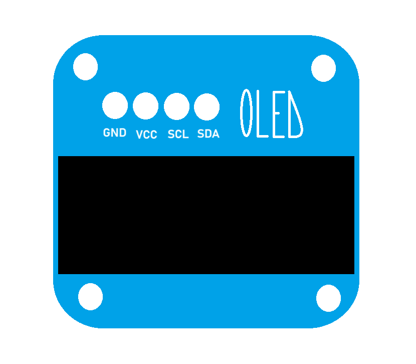
The pinout for a typical I2C-based OLED module is as follows:
| Pin Name | Description |
|---|---|
| VCC | Power supply (3.3V or 5V) |
| GND | Ground |
| SCL | Serial Clock Line for I2C communication |
| SDA | Serial Data Line for I2C communication |
For SPI-based OLED modules, the pinout may include additional pins such as CS (Chip Select) and DC (Data/Command).
Usage Instructions
How to Use the OLED in a Circuit
Connect the OLED to the Arduino UNO:
- For I2C communication:
- Connect
VCCto the 5V pin on the Arduino. - Connect
GNDto the GND pin on the Arduino. - Connect
SCLto the A5 pin (or SCL pin on newer boards). - Connect
SDAto the A4 pin (or SDA pin on newer boards).
- Connect
- For SPI communication, refer to the specific pinout of your OLED module.
- For I2C communication:
Install Required Libraries:
- Use the Arduino IDE to install the
Adafruit_GFXandAdafruit_SSD1306libraries. These libraries provide functions for controlling the OLED.
- Use the Arduino IDE to install the
Upload Example Code:
- Use the following sample code to display text on the OLED:
#include <Adafruit_GFX.h>       // Graphics library for OLED
#include <Adafruit_SSD1306.h>  // OLED driver library

#define SCREEN_WIDTH 128        // OLED display width, in pixels
#define SCREEN_HEIGHT 64        // OLED display height, in pixels

// Declaration for an SSD1306 display connected via I2C
#define OLED_RESET -1           // Reset pin (not used with I2C)
Adafruit_SSD1306 display(SCREEN_WIDTH, SCREEN_HEIGHT, &Wire, OLED_RESET);

void setup() {
  // Initialize the display
  if (!display.begin(SSD1306_I2C_ADDRESS, 0x3C)) {
    // Check if the display is connected
    Serial.println(F("SSD1306 allocation failed"));
    for (;;); // Don't proceed, loop forever
  }

  display.clearDisplay();        // Clear the buffer
  display.setTextSize(1);        // Set text size (1 = small, 2 = medium, etc.)
  display.setTextColor(SSD1306_WHITE); // Set text color
  display.setCursor(0, 0);       // Set cursor position
  display.println(F("Hello, OLED!")); // Print text to display
  display.display();             // Display the text
}

void loop() {
  // Nothing to do here
}
Important Considerations and Best Practices
- Power Supply: Ensure the OLED module is powered within its operating voltage range (3.3V to 5V). Exceeding this range may damage the display.
- I2C Address: The default I2C address for most OLED modules is
0x3C. If the display does not work, check the address using an I2C scanner sketch. - Contrast and Brightness: Adjust the brightness settings in the code to optimize power consumption and display longevity.
- Wiring: Double-check all connections to avoid short circuits or incorrect wiring.
Troubleshooting and FAQs
Common Issues and Solutions
The OLED does not display anything:
- Verify the wiring and ensure all connections are secure.
- Check the I2C address in the code. Use an I2C scanner to confirm the address.
- Ensure the required libraries (
Adafruit_GFXandAdafruit_SSD1306) are installed and up to date.
The display flickers or shows distorted graphics:
- Ensure the power supply is stable and sufficient for the OLED module.
- Check for loose connections or interference in the I2C/SPI lines.
The text or graphics are not visible:
- Increase the brightness in the code.
- Ensure the text size and cursor position are set correctly.
FAQs
Q: Can I use the OLED with a 3.3V microcontroller?
A: Yes, most OLED modules are compatible with both 3.3V and 5V logic levels. Check the module's datasheet to confirm.
Q: How do I display custom graphics on the OLED?
A: Use the Adafruit_GFX library to draw shapes, lines, and bitmaps. You can also use online tools to convert images into bitmap arrays for display.
Q: Can I use multiple OLEDs with one Arduino?
A: Yes, you can use multiple OLEDs by assigning unique I2C addresses or using separate SPI chip select pins.
By following this documentation, you can successfully integrate and use an OLED display in your Arduino projects.