How to Use flame sensor: Examples, Pinouts, and Specs
Introduction
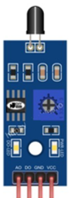
The Flame Sensor (Manufacturer Part ID: FLAME SENSOR) by Arduino is a device designed to detect the presence of a flame or fire. It is commonly used in safety applications to ensure that a flame is present in a burner or to detect fire in a given area. This sensor is highly sensitive to flame and infrared light, making it an essential component in fire detection systems, safety alarms, and various automation projects.
Explore Projects Built with flame sensor
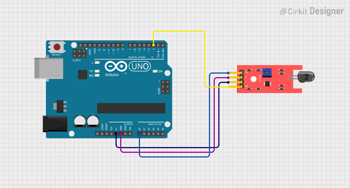
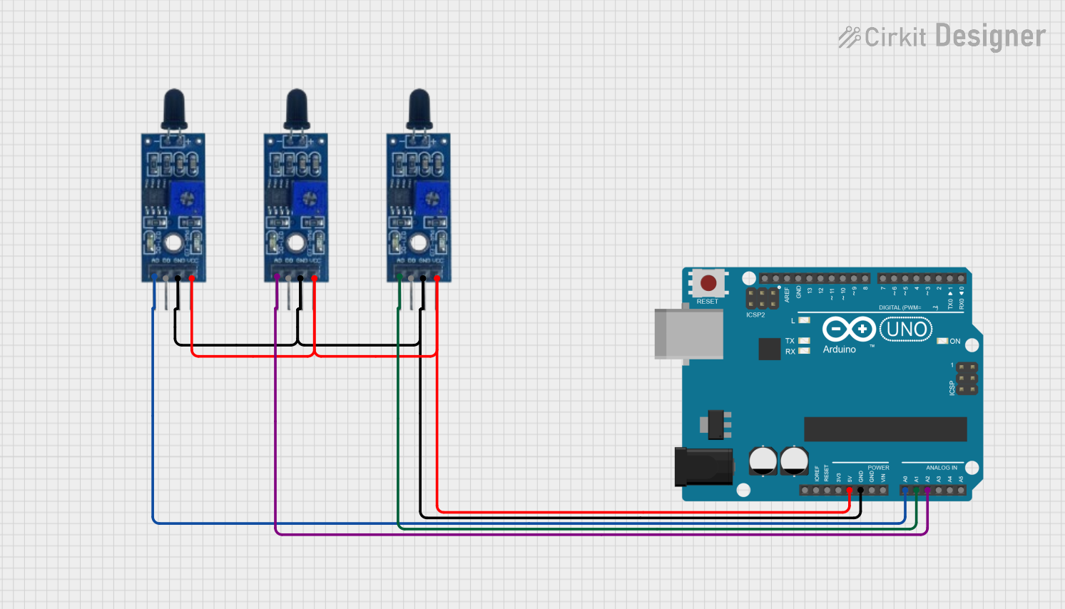
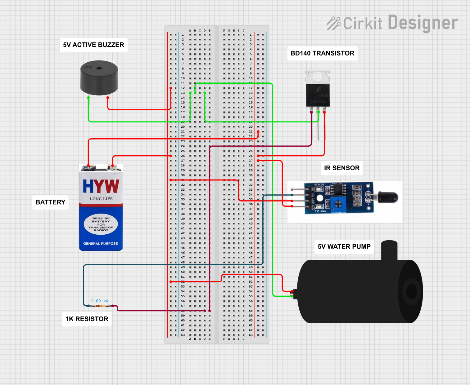
Explore Projects Built with flame sensor
Technical Specifications
Key Technical Details
| Parameter | Value |
|---|---|
| Operating Voltage | 3.3V - 5V |
| Current Consumption | 20mA |
| Detection Range | Up to 100 cm (depending on flame size) |
| Detection Angle | 60 degrees |
| Output Type | Digital and Analog |
| Operating Temperature | -25°C to 85°C |
Pin Configuration and Descriptions
| Pin Number | Pin Name | Description |
|---|---|---|
| 1 | VCC | Power supply (3.3V - 5V) |
| 2 | GND | Ground |
| 3 | A0 | Analog output (provides a variable voltage based on flame intensity) |
| 4 | D0 | Digital output (high when flame is detected, low otherwise) |
| 5 | EN | Enable pin (used to enable or disable the sensor) |
Usage Instructions
How to Use the Component in a Circuit
- Power Supply: Connect the VCC pin to a 3.3V or 5V power supply and the GND pin to the ground of your circuit.
- Analog Output: Connect the A0 pin to an analog input pin on your microcontroller (e.g., Arduino) to read the flame intensity.
- Digital Output: Connect the D0 pin to a digital input pin on your microcontroller to detect the presence of a flame.
- Enable Pin: Optionally, connect the EN pin to a digital output pin on your microcontroller to enable or disable the sensor.
Important Considerations and Best Practices
- Placement: Ensure the sensor is placed in a location where it has a clear line of sight to the area being monitored for flames.
- Calibration: Adjust the sensitivity of the sensor using the onboard potentiometer to suit your specific application.
- Power Supply: Use a stable power supply to avoid false readings.
- Interference: Avoid placing the sensor near sources of infrared light other than the flame to prevent false detections.
Example Circuit with Arduino UNO
/*
  Flame Sensor Example with Arduino UNO
  This example reads the digital and analog outputs of the flame sensor
  and prints the values to the Serial Monitor.
*/

const int flameDigitalPin = 2; // Digital pin connected to D0
const int flameAnalogPin = A0; // Analog pin connected to A0

void setup() {
  pinMode(flameDigitalPin, INPUT); // Set digital pin as input
  Serial.begin(9600); // Initialize serial communication
}

void loop() {
  int flameDigital = digitalRead(flameDigitalPin); // Read digital output
  int flameAnalog = analogRead(flameAnalogPin); // Read analog output

  Serial.print("Digital Output: ");
  Serial.println(flameDigital); // Print digital output value
  Serial.print("Analog Output: ");
  Serial.println(flameAnalog); // Print analog output value

  delay(500); // Wait for 500 milliseconds
}
Troubleshooting and FAQs
Common Issues Users Might Face
False Positives: The sensor detects a flame when there is none.
- Solution: Adjust the sensitivity using the onboard potentiometer. Ensure there are no other sources of infrared light in the sensor's field of view.
No Detection: The sensor does not detect a flame.
- Solution: Check the power supply connections. Ensure the flame is within the detection range and angle. Adjust the sensitivity if necessary.
Unstable Readings: The sensor provides fluctuating readings.
- Solution: Use a stable power supply. Ensure the sensor is not exposed to rapid changes in ambient light or temperature.
FAQs
Q1: Can the flame sensor detect other sources of infrared light?
- A1: Yes, the flame sensor is sensitive to infrared light, so it may detect other sources of infrared radiation. It is important to place the sensor in a location where it primarily detects the flame.
Q2: How do I adjust the sensitivity of the flame sensor?
- A2: The sensitivity can be adjusted using the onboard potentiometer. Turn the potentiometer clockwise to increase sensitivity and counterclockwise to decrease sensitivity.
Q3: What is the maximum distance the flame sensor can detect a flame?
- A3: The detection range is up to 100 cm, depending on the size and intensity of the flame.
Q4: Can I use the flame sensor outdoors?
- A4: The flame sensor can be used outdoors, but it should be protected from direct exposure to weather conditions such as rain and extreme temperatures.
By following this documentation, users can effectively integrate the Arduino Flame Sensor into their projects, ensuring reliable flame detection and enhancing safety measures.