How to Use Blue Code A: Examples, Pinouts, and Specs
Introduction
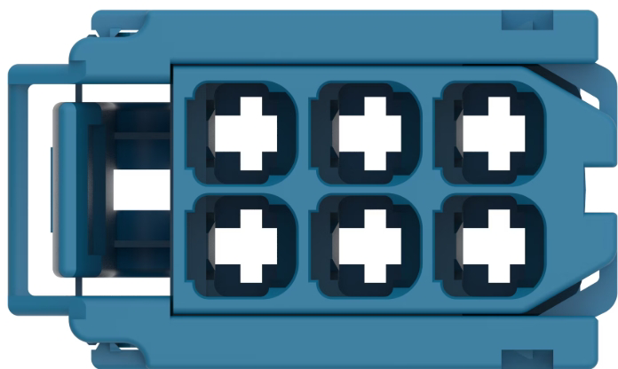
Blue Code A, manufactured by TE Connectivity (Part ID: 8-968970-1), is a specialized coding system designed to represent binary data in electronic systems. It is commonly used in communication protocols, data transmission, and digital signal processing. This component ensures efficient and reliable encoding and decoding of binary information, making it an essential part of modern electronic systems.
Explore Projects Built with Blue Code A
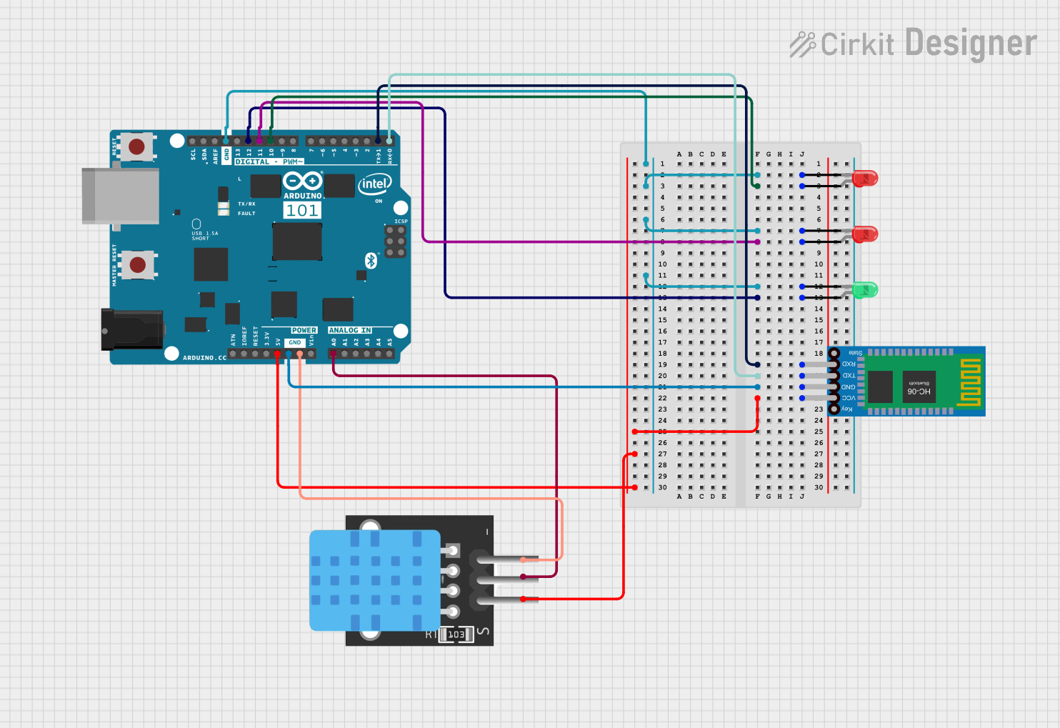
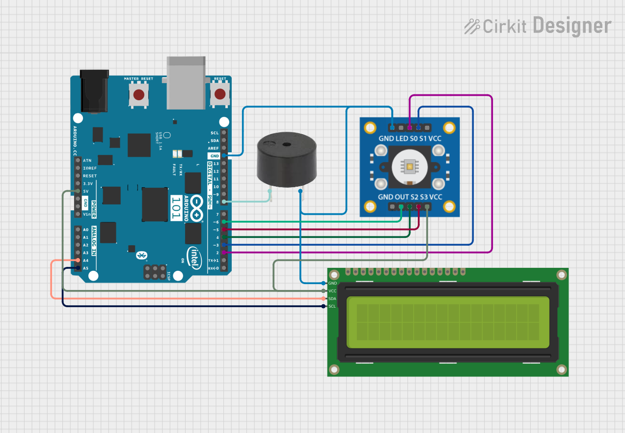
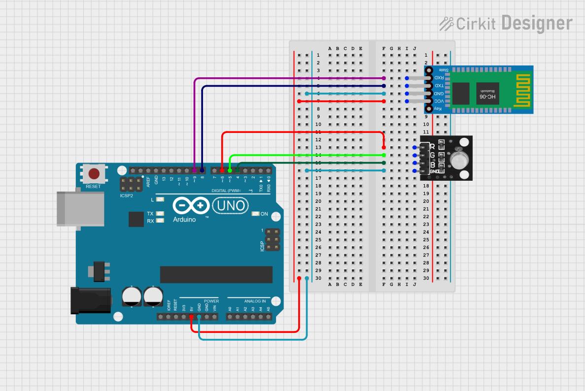
Explore Projects Built with Blue Code A
Common Applications and Use Cases
- Data Transmission: Used in serial communication protocols to encode binary data for error-free transmission.
- Digital Signal Processing: Facilitates the conversion of binary data into a format suitable for processing.
- Embedded Systems: Integrated into microcontroller-based systems for encoding and decoding data.
- Communication Protocols: Plays a critical role in protocols like UART, SPI, and I2C for data integrity.
Technical Specifications
Below are the key technical details and pin configuration for Blue Code A:
Key Technical Details
| Parameter | Value |
|---|---|
| Manufacturer | TE Connectivity |
| Part ID | 8-968970-1 |
| Operating Voltage | 3.3V to 5V |
| Current Consumption | 10 mA (typical) |
| Data Encoding Format | Binary |
| Operating Temperature | -40°C to +85°C |
| Communication Protocols | UART, SPI, I2C |
| Package Type | DIP/SMD |
Pin Configuration and Descriptions
| Pin Number | Pin Name | Description |
|---|---|---|
| 1 | VCC | Power supply input (3.3V to 5V). |
| 2 | GND | Ground connection. |
| 3 | DATA_IN | Input pin for binary data to be encoded. |
| 4 | DATA_OUT | Output pin for encoded binary data. |
| 5 | CLK | Clock signal input for synchronization. |
| 6 | ENABLE | Enable pin to activate the component. |
Usage Instructions
How to Use Blue Code A in a Circuit
- Power Supply: Connect the VCC pin to a 3.3V or 5V power source and the GND pin to the ground.
- Data Input: Feed binary data into the DATA_IN pin. Ensure the data format matches the component's encoding requirements.
- Clock Signal: Provide a clock signal to the CLK pin for proper synchronization.
- Enable the Component: Set the ENABLE pin to HIGH to activate the component.
- Data Output: Retrieve the encoded binary data from the DATA_OUT pin.
Important Considerations and Best Practices
- Voltage Levels: Ensure the operating voltage is within the specified range (3.3V to 5V) to avoid damage.
- Clock Signal: Use a stable clock signal to maintain synchronization and prevent data errors.
- Decoupling Capacitor: Place a 0.1 µF decoupling capacitor near the VCC pin to filter out noise.
- Signal Integrity: Use short and shielded wires for DATA_IN and DATA_OUT to minimize interference.
Example: Connecting Blue Code A to an Arduino UNO
Below is an example of how to interface Blue Code A with an Arduino UNO for encoding binary data:
// Example: Interfacing Blue Code A with Arduino UNO
// Manufacturer: TE Connectivity
// Part ID: 8-968970-1

#define DATA_IN_PIN 2    // Arduino pin connected to Blue Code A's DATA_IN
#define DATA_OUT_PIN 3   // Arduino pin connected to Blue Code A's DATA_OUT
#define ENABLE_PIN 4     // Arduino pin connected to Blue Code A's ENABLE
#define CLK_PIN 5        // Arduino pin connected to Blue Code A's CLK

void setup() {
  pinMode(DATA_IN_PIN, OUTPUT);  // Set DATA_IN as output
  pinMode(DATA_OUT_PIN, INPUT); // Set DATA_OUT as input
  pinMode(ENABLE_PIN, OUTPUT);  // Set ENABLE as output
  pinMode(CLK_PIN, OUTPUT);     // Set CLK as output

  digitalWrite(ENABLE_PIN, HIGH); // Enable Blue Code A
  Serial.begin(9600);             // Initialize serial communication
}

void loop() {
  digitalWrite(CLK_PIN, HIGH);  // Generate clock signal
  delay(1);                     // Short delay for synchronization
  digitalWrite(CLK_PIN, LOW);

  digitalWrite(DATA_IN_PIN, HIGH); // Send binary data (example: HIGH)
  delay(10);                       // Wait for encoding process

  int encodedData = digitalRead(DATA_OUT_PIN); // Read encoded data
  Serial.println(encodedData);                 // Print encoded data to Serial Monitor
  delay(1000);                                 // Wait before next iteration
}
Troubleshooting and FAQs
Common Issues and Solutions
No Output from DATA_OUT Pin:
- Cause: ENABLE pin is not set to HIGH.
- Solution: Ensure the ENABLE pin is connected to a HIGH signal.
Data Corruption:
- Cause: Unstable clock signal or noisy environment.
- Solution: Use a stable clock source and shielded cables for data lines.
Overheating:
- Cause: Operating voltage exceeds the specified range.
- Solution: Verify the power supply voltage is within 3.3V to 5V.
Component Not Responding:
- Cause: Incorrect pin connections.
- Solution: Double-check all connections against the pin configuration table.
FAQs
Q: Can Blue Code A operate at 3.3V?
- A: Yes, it supports an operating voltage range of 3.3V to 5V.
Q: What is the maximum clock frequency supported?
- A: The maximum clock frequency is 1 MHz.
Q: Is Blue Code A compatible with SPI communication?
- A: Yes, it can be integrated into SPI-based systems.
Q: Can I use Blue Code A in outdoor environments?
- A: Yes, it operates reliably within the temperature range of -40°C to +85°C.
This concludes the documentation for Blue Code A. For further assistance, refer to the manufacturer's datasheet or contact TE Connectivity support.