
How to Use Raspberry Pi Pinout Diagram: Examples, Pinouts, and Specs
 Design with Raspberry Pi Pinout Diagram in Cirkit Designer
Introduction
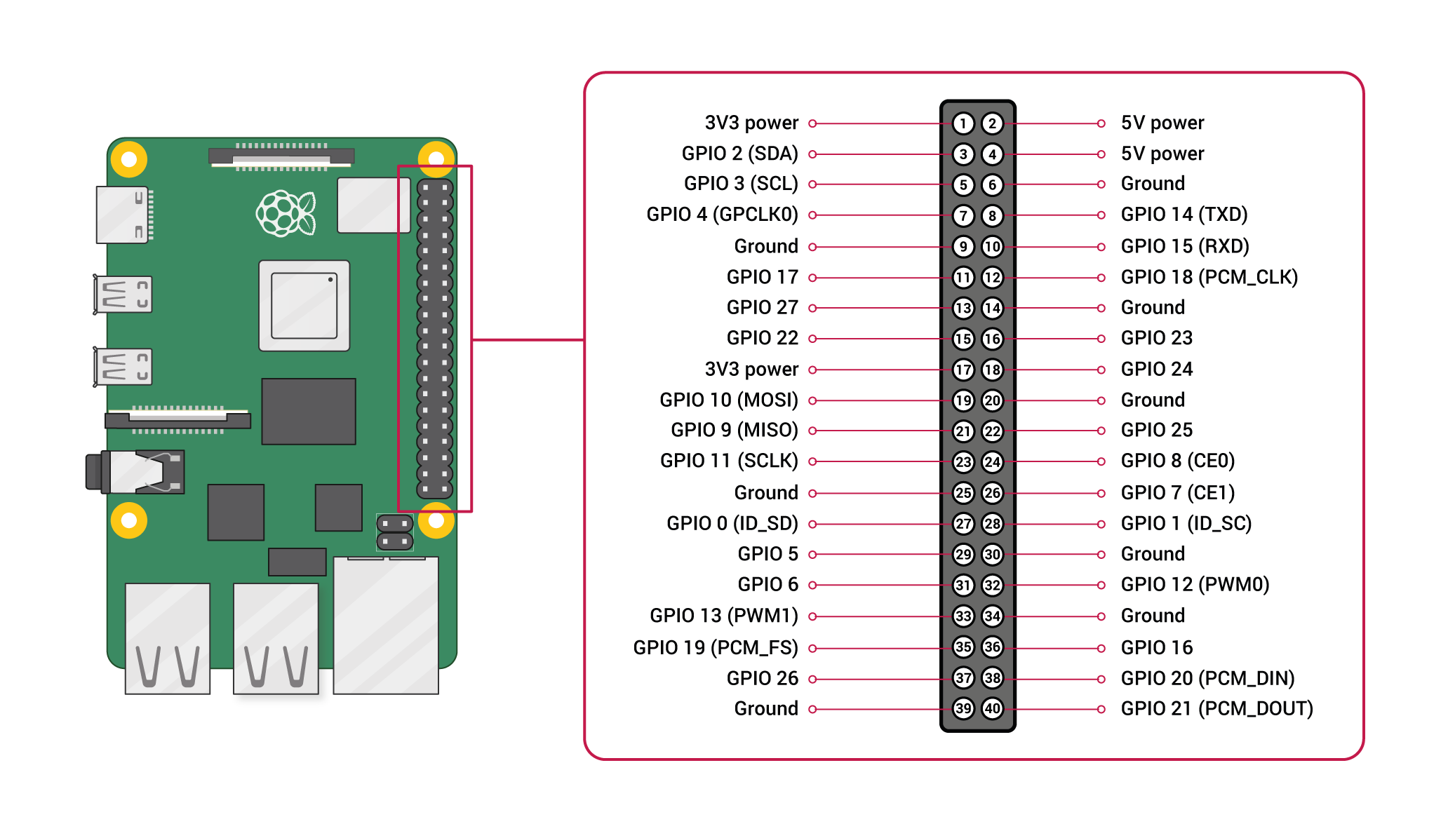
The Raspberry Pi Pinout Diagram is an essential reference for developers and hobbyists working with the Raspberry Pi single-board computer. This diagram provides a visual representation of the General Purpose Input/Output (GPIO) pins, detailing their functions, characteristics, and how they can be utilized in various projects. Common applications include interfacing with sensors, controlling motors, connecting to other integrated circuits, and building Internet of Things (IoT) devices.
Explore Projects Built with Raspberry Pi Pinout Diagram
 Open Project in Cirkit Designer
 Open Project in Cirkit Designer
 Open Project in Cirkit Designer
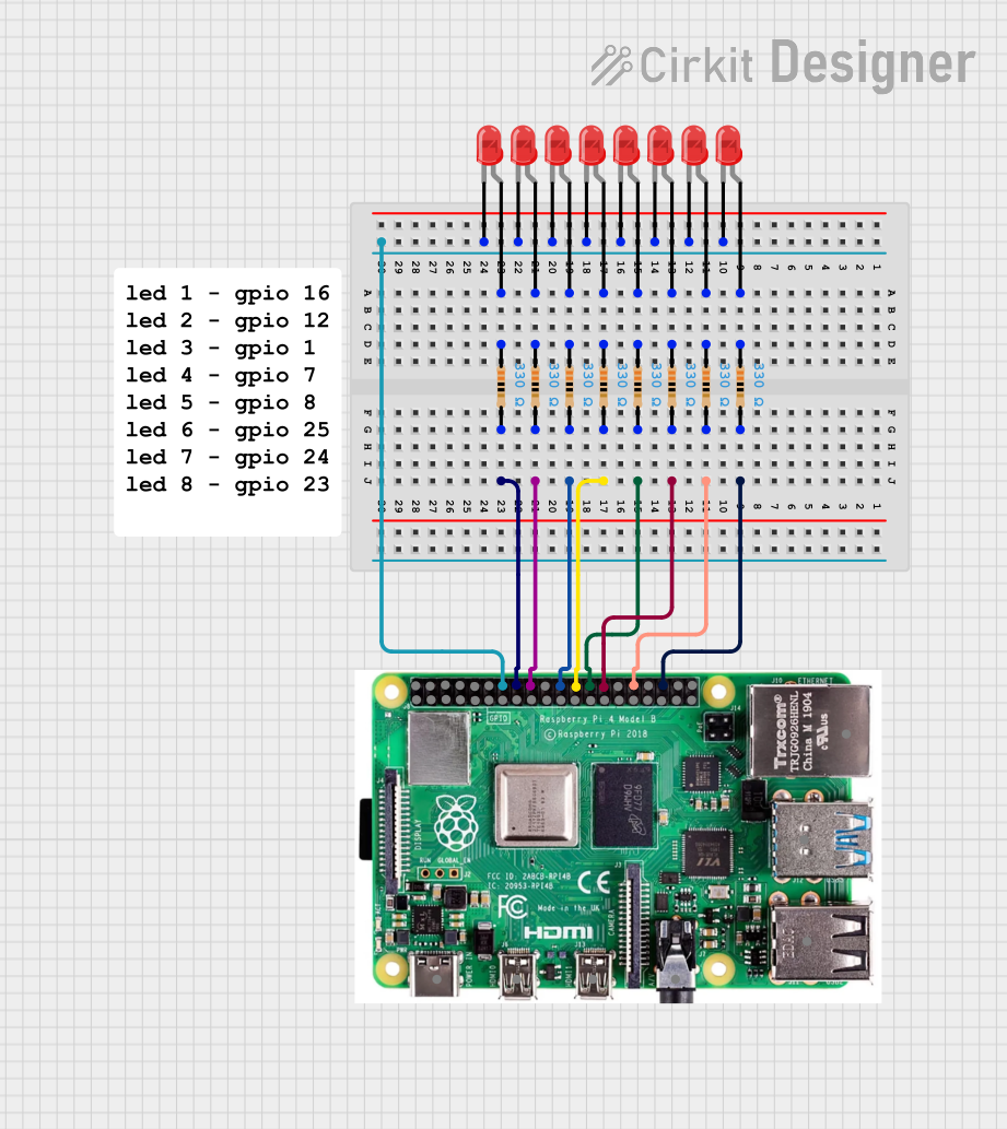
 Open Project in Cirkit Designer
Explore Projects Built with Raspberry Pi Pinout Diagram

 Open Project in Cirkit Designer
 Open Project in Cirkit Designer
 Open Project in Cirkit Designer
 Open Project in Cirkit Designer
Technical Specifications
General Characteristics
- GPIO Pins: Multiple pins with various functions including power, ground, and data.
- Voltage Levels: 3.3V logic level (5V tolerant on certain pins).
- Current Limit: Recommended maximum of 16mA per GPIO pin.
Pin Configuration and Descriptions
The following table provides an overview of the pin configuration for a typical Raspberry Pi model (e.g., Raspberry Pi 4 Model B). Please note that pin configurations may vary slightly between different Raspberry Pi models.
| Pin Number | Name | Description |
|---|---|---|
| 1 | 3V3 | 3.3V Power Rail |
| 2 | 5V | 5V Power Rail |
| 3 | GPIO2 | SDA (I2C) |
| 4 | 5V | 5V Power Rail |
| 5 | GPIO3 | SCL (I2C) |
| 6 | GND | Ground |
| ... | ... | ... |
| 39 | GND | Ground |
| 40 | GPIO21 | SPI MISO |
Note: This table is not exhaustive. Refer to the official Raspberry Pi documentation for a complete pinout diagram.
Usage Instructions
Interfacing with the GPIO Pins
- Identify the Pins: Refer to the pinout diagram to identify the pins needed for your project.
- Configure the Pins: Set the pins as input or output depending on your requirements.
- Connect the Components: Attach sensors, actuators, or other components to the GPIO pins.
- Power Considerations: Ensure that the power requirements of your peripherals do not exceed the power ratings of the GPIO pins.
Best Practices
- Use resistors to limit current and prevent damage to the GPIO pins.
- Avoid connecting high-power devices directly to the GPIO pins.
- Utilize external power sources for components that require more current than the GPIO pins can provide.
- Always shutdown the Raspberry Pi before connecting or disconnecting components to prevent short circuits.
Troubleshooting and FAQs
Common Issues
- Non-responsive GPIO Pins: Ensure that the pins are correctly configured in your code and that all connections are secure.
- Overcurrent Damage: If a GPIO pin stops working, it may be due to drawing too much current. Check the current draw of connected components.
FAQs
Q: Can I use all GPIO pins for general input/output tasks? A: Most GPIO pins can be used for general purposes, but some have specialized functions (e.g., SPI, I2C, UART). Refer to the pinout diagram for details.
Q: What is the maximum voltage that can be applied to a GPIO pin? A: The maximum voltage for a GPIO pin is 3.3V. Exceeding this voltage can damage the Raspberry Pi.
Q: How can I protect the GPIO pins from damage? A: Use voltage level shifters for interfacing with 5V devices, and employ current-limiting resistors to protect against overcurrent situations.
Example Code for Raspberry Pi and Arduino UNO Communication
Below is an example of how to set up serial communication between a Raspberry Pi and an Arduino UNO. This code snippet would be run on the Raspberry Pi.
import serial
import time
Set up the serial connection (adjust '/dev/ttyACM0' to the port where your Arduino is connected)
ser = serial.Serial('/dev/ttyACM0', 9600) time.sleep(2) # Wait for the connection to be established
Send data to the Arduino
ser.write(b'Hello Arduino!')
Read data from the Arduino
while True: if ser.in_waiting > 0: incoming_data = ser.readline().decode('utf-8').rstrip() print(f"Data received: {incoming_data}")
*Note: Ensure that the Raspberry Pi and Arduino are connected using the correct TX and RX pins and that the ground pins are connected to establish a common ground.*

Remember to consult the Raspberry Pi and Arduino UNO documentation for detailed information on pinouts and serial communication setup.