Cirkit Designer Logo
Cirkit Designer
Your all-in-one circuit design IDE
Home / 
Component Documentation

How to Use 5v Type C Dc Socket: Examples, Pinouts, and Specs

Image of 5v Type C Dc Socket
Cirkit Designer LogoDesign with 5v Type C Dc Socket in Cirkit Designer

Introduction

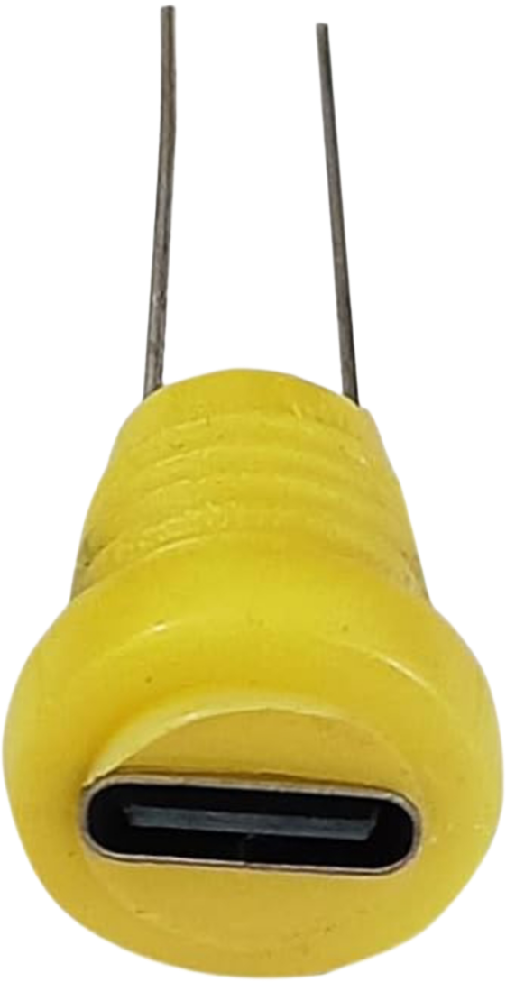
The 5V Type C DC Socket (YP-12345) is a modern power connector designed to interface with USB Type-C power sources. This component is essential for electronic devices that require a 5V DC power input. It is commonly used in portable electronics, embedded systems, and IoT devices due to its compact size and reliability. The Type C connector is reversible, which makes it user-friendly, as it can be inserted in any orientation.

Explore Projects Built with 5v Type C Dc Socket

Use Cirkit Designer to design, explore, and prototype these projects online. Some projects support real-time simulation. Click "Open Project" to start designing instantly!
Dual 5V Power Supply Distribution Circuit with Toggle Switch Control
Image of rfdriver: A project utilizing 5v Type C Dc Socket in a practical application
This circuit consists of two 5V 5A power supplies connected to an AC wall plug point, providing DC output through a 12-way connector. The ground connections from both power supplies are interconnected and also connected to the ground pins of two toggle switches. The DC outputs from the power supplies are separately connected to different pins on the 12-way connector, with each power supply output being switchable via one of the toggle switches.
Cirkit Designer LogoOpen Project in Cirkit Designer
Battery-Powered USB Charger with LED Indicator and DC Motor
Image of Copy of Hand Crank mobile charger : A project utilizing 5v Type C Dc Socket in a practical application
This circuit converts AC power to DC using a bridge rectifier and regulates the voltage to 5V with a 7805 voltage regulator. It powers a USB port and indicates power status with an LED, while also providing a charging interface through a multi-charging cable.
Cirkit Designer LogoOpen Project in Cirkit Designer
USB Type-C Powered LED Circuit with Resistor
Image of Scheme1: A project utilizing 5v Type C Dc Socket in a practical application
This circuit consists of a USB Type-C port providing power to a red LED through a 1000 Ohm resistor. The resistor limits the current flowing through the LED, which lights up when the circuit is powered.
Cirkit Designer LogoOpen Project in Cirkit Designer
Raspberry Pi 3B Powered 15.6-inch Touchscreen Display with USB Type-C Power Delivery
Image of Pi Touch Screen Kiosk: A project utilizing 5v Type C Dc Socket in a practical application
This circuit powers a 15.6-inch capacitive touch display and a Raspberry Pi 3B using a USB Type C power delivery breakout and two buck converters. The Raspberry Pi connects to the display via HDMI and USB for touch functionality, while the power delivery breakout provides regulated power to both the display and the Raspberry Pi through the buck converters.
Cirkit Designer LogoOpen Project in Cirkit Designer

Explore Projects Built with 5v Type C Dc Socket

Use Cirkit Designer to design, explore, and prototype these projects online. Some projects support real-time simulation. Click "Open Project" to start designing instantly!
Image of rfdriver: A project utilizing 5v Type C Dc Socket in a practical application
Dual 5V Power Supply Distribution Circuit with Toggle Switch Control
This circuit consists of two 5V 5A power supplies connected to an AC wall plug point, providing DC output through a 12-way connector. The ground connections from both power supplies are interconnected and also connected to the ground pins of two toggle switches. The DC outputs from the power supplies are separately connected to different pins on the 12-way connector, with each power supply output being switchable via one of the toggle switches.
Cirkit Designer LogoOpen Project in Cirkit Designer
Image of Copy of Hand Crank mobile charger : A project utilizing 5v Type C Dc Socket in a practical application
Battery-Powered USB Charger with LED Indicator and DC Motor
This circuit converts AC power to DC using a bridge rectifier and regulates the voltage to 5V with a 7805 voltage regulator. It powers a USB port and indicates power status with an LED, while also providing a charging interface through a multi-charging cable.
Cirkit Designer LogoOpen Project in Cirkit Designer
Image of Scheme1: A project utilizing 5v Type C Dc Socket in a practical application
USB Type-C Powered LED Circuit with Resistor
This circuit consists of a USB Type-C port providing power to a red LED through a 1000 Ohm resistor. The resistor limits the current flowing through the LED, which lights up when the circuit is powered.
Cirkit Designer LogoOpen Project in Cirkit Designer
Image of Pi Touch Screen Kiosk: A project utilizing 5v Type C Dc Socket in a practical application
Raspberry Pi 3B Powered 15.6-inch Touchscreen Display with USB Type-C Power Delivery
This circuit powers a 15.6-inch capacitive touch display and a Raspberry Pi 3B using a USB Type C power delivery breakout and two buck converters. The Raspberry Pi connects to the display via HDMI and USB for touch functionality, while the power delivery breakout provides regulated power to both the display and the Raspberry Pi through the buck converters.
Cirkit Designer LogoOpen Project in Cirkit Designer

Common Applications and Use Cases

  • Charging smartphones, tablets, and other portable devices
  • Powering Raspberry Pi or other single-board computers
  • Serving as a power input for DIY electronics projects
  • Providing power for USB-powered gadgets and accessories

Technical Specifications

Key Technical Details

  • Rated Voltage: 5V DC
  • Rated Current: Up to 3A
  • Operating Temperature: -20°C to 85°C
  • Durability: 10,000 cycles
  • Compliance: USB Type-C Specification Release 1.1

Pin Configuration and Descriptions

Pin Number Description Notes
1 VBUS (5V) Power delivery (positive)
2 CC1 Channel configuration pin
3 D- USB 2.0 differential pair
4 D+ USB 2.0 differential pair
5 SBU1 Sideband use
6 VBUS (5V) Power delivery (positive)
7 GND Ground (negative)
8 GND Ground (negative)
9 CC2 Channel configuration pin
10 SBU2 Sideband use

Note: The Type C connector has more pins, but only the relevant power and ground pins are listed for this application.

Usage Instructions

How to Use the Component in a Circuit

  1. Power Connection: Connect the VBUS pin to the positive terminal of your power source and the GND pin to the negative terminal.
  2. Data Connection (if applicable): If data transfer is required, connect the D+ and D- pins to the appropriate data lines on your device.
  3. Mounting: Secure the socket onto your PCB or enclosure, ensuring a stable and reliable connection.

Important Considerations and Best Practices

  • Voltage Regulation: Ensure that the power source does not exceed the 5V rating to prevent damage.
  • Current Limiting: Incorporate a fuse or current-limiting resistor to protect against overcurrent conditions.
  • Cable Quality: Use high-quality USB Type-C cables to ensure stable power delivery and data transfer.
  • PCB Design: Follow the manufacturer's footprint and soldering guidelines for PCB mounting.

Troubleshooting and FAQs

Common Issues

  • No Power: Check the cable and connections for any signs of damage or loose contacts.
  • Intermittent Connection: Inspect the socket for debris or damage. Ensure the USB Type-C plug is fully inserted.
  • Overheating: Ensure that the current draw does not exceed the rated 3A limit.

Solutions and Tips for Troubleshooting

  • Secure Connections: Double-check solder joints and wiring for any potential faults.
  • Cable Replacement: Try a different USB Type-C cable to rule out cable issues.
  • Power Source Verification: Use a multimeter to verify that the power source is delivering 5V as expected.

FAQs

Q: Can I use this socket for data transfer? A: Yes, the socket supports USB 2.0 data transfer using the D+ and D- pins.

Q: Is this socket compatible with USB PD (Power Delivery)? A: The socket supports up to 3A of current, which is within the USB PD specification for certain power profiles. However, full USB PD compatibility requires additional circuitry for power negotiation.

Q: How do I mount this socket onto a PCB? A: Follow the footprint and soldering guidelines provided by the manufacturer, YP, for the part ID 12345.

Q: What is the durability of this socket? A: The socket is rated for 10,000 insertion/removal cycles.

Example Code for Arduino UNO

// Example code to power an Arduino UNO through the 5V Type C DC Socket (YP-12345)

void setup() {
  // Initialize digital pin LED_BUILTIN as an output.
  pinMode(LED_BUILTIN, OUTPUT);
}

void loop() {
  // Turn the LED on (HIGH is the voltage level)
  digitalWrite(LED_BUILTIN, HIGH);
  // Wait for a second
  delay(1000);
  // Turn the LED off by making the voltage LOW
  digitalWrite(LED_BUILTIN, LOW);
   // Wait for a second
  delay(1000);
}

// Note: This code assumes that the Arduino UNO is powered through the 5V pin
// using the 5V Type C DC Socket. Ensure that the power supply connected to the
// socket does not exceed 5V and 3A to avoid damaging the Arduino UNO.

Please note that the example code provided is a simple blink sketch to demonstrate powering an Arduino UNO through the 5V Type C DC Socket. It does not involve USB data transfer capabilities of the socket.