How to Use PSU: Examples, Pinouts, and Specs
Introduction
A Power Supply Unit (PSU) is an essential electronic component that converts electrical power from an outlet into usable power for a computer or other electronic devices. It ensures the delivery of the correct voltage and current required by the connected components, protecting them from power surges and fluctuations. PSUs are available in various configurations to meet the needs of different devices and systems.
Explore Projects Built with PSU


Explore Projects Built with PSU
Common Applications and Use Cases
- Desktop computers and servers
- Embedded systems and microcontrollers
- Industrial equipment and machinery
- Consumer electronics (e.g., gaming consoles, televisions)
- Prototyping and testing circuits in laboratories
Technical Specifications
Below are the general technical specifications for a standard PSU. Specifications may vary depending on the model and manufacturer.
Key Technical Details
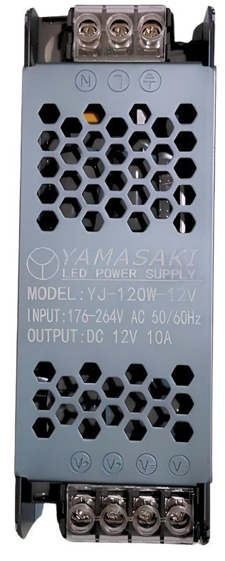
- Input Voltage: 100-240V AC (typical for universal PSUs)
- Output Voltage: Common outputs include 3.3V, 5V, 12V DC
- Output Current: Varies by model, typically ranges from 1A to 50A
- Power Rating: 100W to 1200W (or higher for high-performance systems)
- Efficiency: 80% or higher (certified models may have 80 PLUS ratings)
- Protection Features: Overvoltage, overcurrent, short-circuit, and thermal protection
Pin Configuration and Descriptions
The pin configuration of a PSU depends on its type. Below is an example of the pinout for a standard ATX PSU used in computers:
| Pin Number | Signal Name | Description |
|---|---|---|
| 1 | +3.3V | 3.3V DC output |
| 2 | +5V | 5V DC output |
| 3 | +12V | 12V DC output |
| 4 | GND | Ground |
| 5 | PS_ON | Power supply on/off control (active low) |
| 6 | PWR_OK | Power good signal |
| 7 | -12V | -12V DC output |
| 8 | +5VSB | 5V standby power |
Usage Instructions
How to Use the PSU in a Circuit
- Determine Power Requirements: Identify the voltage and current requirements of your device or circuit.
- Connect the PSU:
- Plug the PSU into a compatible AC outlet.
- Use the appropriate output pins to connect the PSU to your device or circuit.
- Ensure proper polarity (positive and ground connections).
- Enable the PSU:
- For ATX PSUs, connect the
PS_ONpin to ground to turn on the power supply. - Verify the
PWR_OKsignal to ensure the PSU is functioning correctly.
- For ATX PSUs, connect the
- Monitor Output: Use a multimeter to confirm the output voltage and current match the requirements.
Important Considerations and Best Practices
- Load Requirements: Ensure the PSU is not overloaded. The total power consumption of connected devices should not exceed the PSU's rated power.
- Ventilation: Place the PSU in a well-ventilated area to prevent overheating.
- Safety: Avoid touching exposed wires or terminals while the PSU is powered on.
- Standby Power: Use the
+5VSBpin for low-power standby applications.
Example: Using a PSU with an Arduino UNO
To power an Arduino UNO using a PSU, follow these steps:
- Identify the Arduino's power input requirements (5V DC).
- Connect the PSU's 5V output to the Arduino's
5Vpin and the ground to theGNDpin. - Ensure the PSU is turned on and delivering the correct voltage.
Here is an example Arduino sketch to test the setup:
// Simple LED Blink Test for Arduino UNO
// Ensure the PSU is providing 5V to the Arduino's 5V and GND pins.

const int ledPin = 13; // Built-in LED pin on Arduino UNO

void setup() {
  pinMode(ledPin, OUTPUT); // Set the LED pin as an output
}

void loop() {
  digitalWrite(ledPin, HIGH); // Turn the LED on
  delay(1000);               // Wait for 1 second
  digitalWrite(ledPin, LOW);  // Turn the LED off
  delay(1000);               // Wait for 1 second
}
Troubleshooting and FAQs
Common Issues and Solutions
- PSU Does Not Turn On:
- Ensure the PSU is connected to a live AC outlet.
- For ATX PSUs, verify that the
PS_ONpin is connected to ground.
- Incorrect Output Voltage:
- Check the load connected to the PSU. An excessive load may cause voltage drops.
- Use a multimeter to measure the output voltage and confirm it matches the specifications.
- Overheating:
- Ensure the PSU is not overloaded.
- Check for proper ventilation and clean any dust from the PSU's fan and vents.
- Device Not Powering On:
- Verify the connections between the PSU and the device.
- Check the
PWR_OKsignal to ensure the PSU is functioning correctly.
FAQs
Q: Can I use a PSU with a higher wattage than my device requires?
A: Yes, a PSU with a higher wattage rating can be used as long as the voltage matches the device's requirements. The device will only draw the power it needs.
Q: How do I test a PSU without connecting it to a device?
A: For ATX PSUs, you can use a paperclip or jumper wire to connect the PS_ON pin to ground. This will turn on the PSU, allowing you to measure the output voltages with a multimeter.
Q: What is the purpose of the +5VSB pin?
A: The +5VSB pin provides standby power, which is useful for powering low-power circuits or maintaining certain functions (e.g., wake-on-LAN) when the PSU is off.
Q: Can I repair a faulty PSU?
A: Repairing a PSU is not recommended unless you have expertise in electronics. Faulty PSUs can be dangerous due to high voltages and stored energy in capacitors.
By following this documentation, you can safely and effectively use a PSU in your projects and troubleshoot common issues.