How to Use ESP32-S2 (42 Pin): Examples, Pinouts, and Specs
Introduction
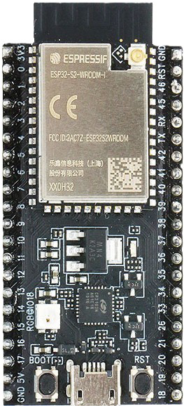
The ESP32-S2-Saola-1R, manufactured by Espressif Systems, is a powerful microcontroller designed for IoT applications. It features integrated Wi-Fi capabilities, Bluetooth LE, and 42 GPIO pins, making it a versatile choice for a wide range of projects. With its high performance, low power consumption, and rich peripheral set, the ESP32-S2 is ideal for smart home devices, wearables, industrial automation, and more.
Explore Projects Built with ESP32-S2 (42 Pin)


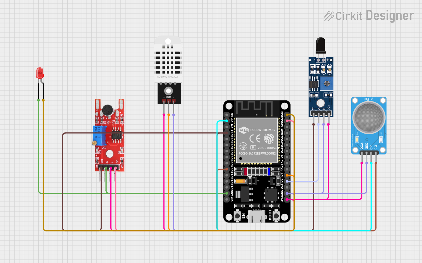
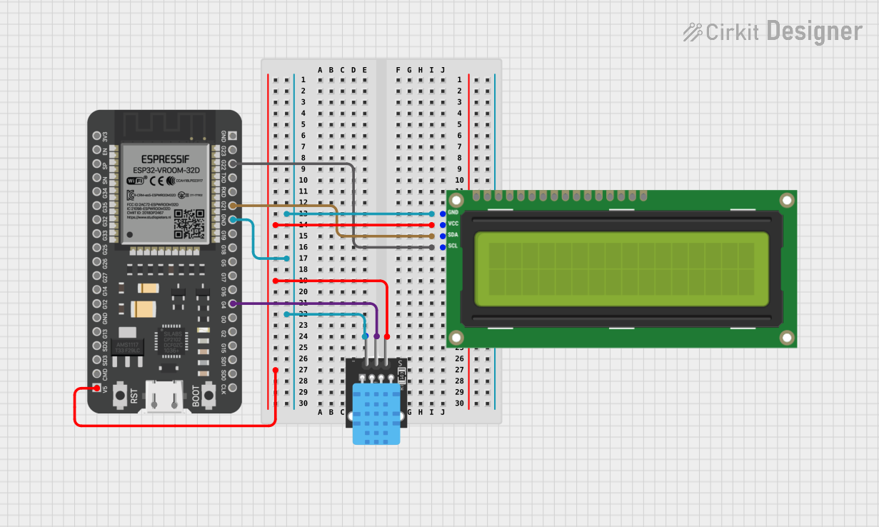
Explore Projects Built with ESP32-S2 (42 Pin)
Common Applications and Use Cases
- IoT devices and smart home automation
- Wearable electronics
- Industrial control systems
- Wireless sensor networks
- Prototyping and development of connected devices
Technical Specifications
The ESP32-S2-Saola-1R is built for performance and flexibility. Below are its key technical details:
Key Technical Details
| Parameter | Specification |
|---|---|
| Microcontroller | Xtensa® 32-bit LX7 single-core CPU |
| Clock Speed | Up to 240 MHz |
| Flash Memory | 4 MB SPI Flash |
| RAM | 320 KB SRAM + 128 KB ROM |
| Wi-Fi | 802.11 b/g/n (2.4 GHz) |
| Bluetooth | Bluetooth LE (Low Energy) |
| GPIO Pins | 42 |
| Operating Voltage | 3.3 V |
| Power Supply Range | 3.0 V to 3.6 V |
| Current Consumption | 5 µA (deep sleep), ~70 mA (active) |
| Interfaces | SPI, I2C, UART, ADC, DAC, PWM, USB OTG |
Pin Configuration and Descriptions
The ESP32-S2-Saola-1R features 42 GPIO pins, each with multiple functions. Below is a summary of the pin configuration:
| Pin Number | Pin Name | Function(s) | Notes |
|---|---|---|---|
| 1 | GND | Ground | Connect to ground |
| 2 | 3V3 | 3.3V Power Output | Power supply for peripherals |
| 3 | GPIO0 | GPIO, Boot Mode Selection | Pull low to enter bootloader |
| 4 | GPIO1 | GPIO, UART TX | Serial communication |
| 5 | GPIO2 | GPIO, UART RX | Serial communication |
| ... | ... | ... | ... |
| 42 | EN | Chip Enable | Active high to enable the chip |
Note: For the full pinout and alternate functions, refer to the official datasheet.
Usage Instructions
The ESP32-S2-Saola-1R is easy to integrate into your projects. Below are the steps to get started:
How to Use the Component in a Circuit
- Power Supply: Provide a stable 3.3V power supply to the
3V3pin. ConnectGNDto the ground of your circuit. - Programming: Use a USB-to-serial adapter or a development board with a USB interface to program the ESP32-S2.
- Boot Mode: To enter bootloader mode, hold the
BOOTbutton (connected to GPIO0) while pressing theENbutton. - Peripherals: Connect sensors, actuators, or other peripherals to the GPIO pins. Use the appropriate interface (SPI, I2C, UART, etc.) for communication.
Important Considerations and Best Practices
- Voltage Levels: Ensure all connected peripherals operate at 3.3V logic levels to avoid damaging the GPIO pins.
- Power Consumption: Use deep sleep mode to minimize power consumption in battery-powered applications.
- Pull-up/Pull-down Resistors: Some GPIO pins require external pull-up or pull-down resistors for proper operation.
- Antenna Placement: For optimal Wi-Fi performance, ensure the onboard antenna is not obstructed by metal or other conductive materials.
Example Code for Arduino UNO Integration
The ESP32-S2 can be programmed using the Arduino IDE. Below is an example of how to blink an LED connected to GPIO2:
// Example: Blink an LED connected to GPIO2 on the ESP32-S2
// Ensure the LED's anode is connected to GPIO2 and cathode to GND.

#define LED_PIN 2  // Define the GPIO pin for the LED

void setup() {
  pinMode(LED_PIN, OUTPUT);  // Set GPIO2 as an output pin
}

void loop() {
  digitalWrite(LED_PIN, HIGH);  // Turn the LED on
  delay(1000);                  // Wait for 1 second
  digitalWrite(LED_PIN, LOW);   // Turn the LED off
  delay(1000);                  // Wait for 1 second
}
Tip: Install the ESP32 board package in the Arduino IDE before uploading the code.
Troubleshooting and FAQs
Common Issues and Solutions
Device Not Detected by Computer
- Ensure the USB cable is functional and supports data transfer.
- Check if the correct COM port is selected in the Arduino IDE or other programming tools.
- Verify that the
BOOTandENbuttons are used correctly for bootloader mode.
Wi-Fi Connection Fails
- Double-check the SSID and password in your code.
- Ensure the Wi-Fi network operates on the 2.4 GHz band (not 5 GHz).
GPIO Pin Not Responding
- Verify that the pin is not being used for another function (e.g., UART, SPI).
- Check for proper pull-up or pull-down resistors if required.
High Power Consumption
- Use deep sleep mode to reduce power usage.
- Disconnect unused peripherals to minimize current draw.
FAQs
Q: Can the ESP32-S2-Saola-1R operate on 5V?
A: No, the ESP32-S2 operates at 3.3V. Connecting 5V to GPIO pins may damage the chip.
Q: How do I reset the ESP32-S2?
A: Press the EN button to reset the microcontroller.
Q: Can I use the ESP32-S2 with MicroPython?
A: Yes, the ESP32-S2 supports MicroPython. Flash the MicroPython firmware to get started.
Q: What is the maximum number of GPIO pins I can use?
A: The ESP32-S2 has 42 GPIO pins, but some may be reserved for specific functions depending on your application.
For additional support, refer to the official Espressif documentation or community forums.