How to Use Adafruit ICM20649: Examples, Pinouts, and Specs
Introduction
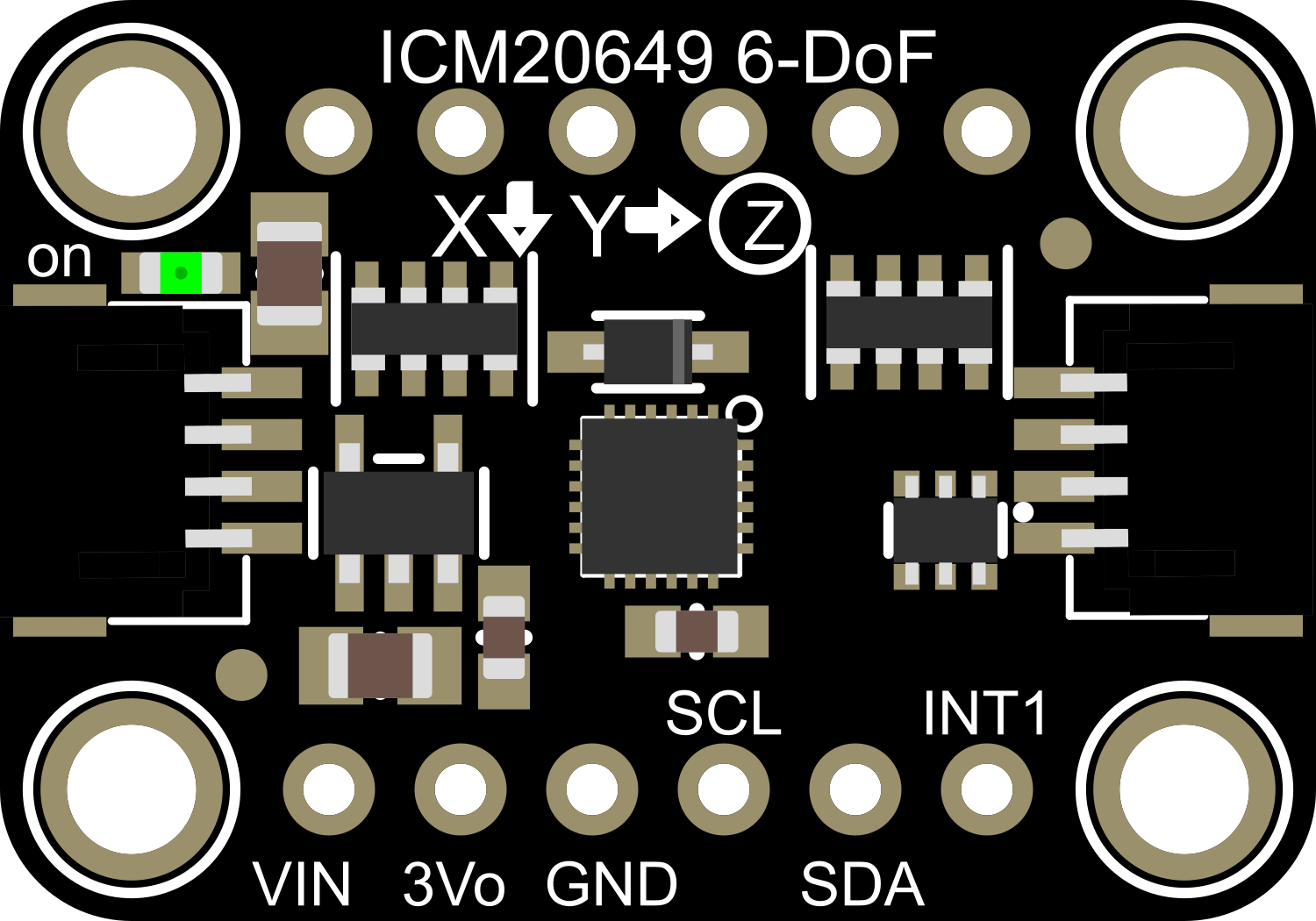
The Adafruit ICM20649 is a high-performance 6-axis motion tracking device that combines a 3-axis gyroscope and a 3-axis accelerometer. This integrated circuit module is designed for applications that require precise motion sensing and orientation tracking, such as drones, gaming devices, and wearable fitness trackers. Its small form factor and low power consumption make it ideal for portable electronics.
Explore Projects Built with Adafruit ICM20649


Explore Projects Built with Adafruit ICM20649
Common Applications and Use Cases
- Motion-enabled game controllers
- Fitness and activity monitoring devices
- Drone stabilization systems
- Orientation tracking for virtual and augmented reality
- Robotics and movement analysis
Technical Specifications
Key Technical Details
- Accelerometer Range: ±4g, ±8g, ±16g, ±30g
- Gyroscope Range: ±250, ±500, ±1000, ±2000 degrees per second (dps)
- Operating Voltage: 1.71V to 3.6V
- Interface: I2C and SPI
- Output Data Rate (ODR): Up to 1125 Hz for gyroscope, 4.5 kHz for accelerometer
Pin Configuration and Descriptions
| Pin Number | Name | Description |
|---|---|---|
| 1 | VDD | Power supply voltage (1.71V to 3.6V) |
| 2 | GND | Ground connection |
| 3 | SCL/SPC | Serial Clock for I2C, Serial Port Clock for SPI |
| 4 | SDA/SDI | Serial Data for I2C, Serial Data Input for SPI |
| 5 | NCS | Chip Select for SPI (active low) |
| 6 | SDO/ADO | Serial Data Output for SPI, I2C Address selection |
| 7 | INT | Interrupt output (active high) |
| 8 | FSYNC | Frame synchronization (optional use) |
Usage Instructions
How to Use the Component in a Circuit
- Power Supply: Connect the VDD pin to a power source between 1.71V and 3.6V, and connect the GND pin to the ground of your circuit.
- Communication Interface: Choose between I2C or SPI for communication with a microcontroller. For I2C, connect SCL to the I2C clock line and SDA to the I2C data line. For SPI, connect SPC to the SPI clock, SDI to the SPI data input, SDO to the SPI data output, and NCS to the SPI chip select.
- Interrupts (Optional): The INT pin can be used to trigger an interrupt on the microcontroller when new data is available or other events occur.
- FSYNC (Optional): The FSYNC pin can be used for frame synchronization in applications that require precise timing of sensor data acquisition.
Important Considerations and Best Practices
- Ensure that the power supply is stable and within the specified voltage range to prevent damage to the ICM20649.
- Use pull-up resistors on the I2C lines if they are not already present on the microcontroller board.
- When using SPI, ensure that the NCS line is held high when the device is not in use.
- For accurate readings, calibrate the sensor for zero offsets and environmental factors.
- Place the sensor away from magnetic fields and components that can cause electrical noise.
Troubleshooting and FAQs
Common Issues Users Might Face
- No Data Output: Ensure that the power supply is correctly connected and within the specified range. Check the communication lines for proper connection and pull-up resistors.
- Inaccurate Readings: Calibrate the sensor, check for nearby magnetic fields, and ensure the sensor is mounted securely without vibrations.
- Communication Errors: Verify the correct communication protocol (I2C/SPI) is selected and that the microcontroller is configured accordingly.
Solutions and Tips for Troubleshooting
- Power Issues: Use a multimeter to check the voltage at the VDD pin.
- Connection Issues: Double-check wiring against the pin configuration table. Use an oscilloscope to verify signals on the communication lines.
- Calibration: Follow the manufacturer's calibration procedure to offset any inaccuracies.
FAQs
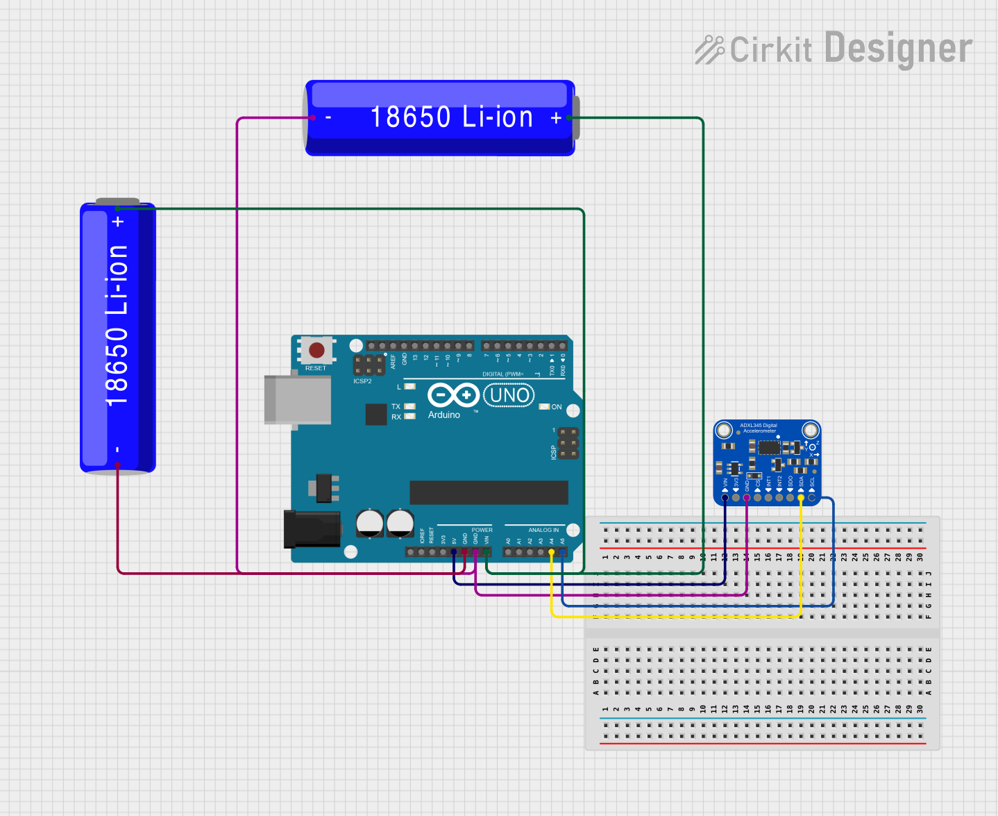
Q: Can the ICM20649 be used with an Arduino UNO? A: Yes, the ICM20649 can be connected to an Arduino UNO via I2C or SPI.
Q: What is the purpose of the FSYNC pin? A: The FSYNC pin is used for frame synchronization, which can be useful in applications requiring precise timing of data collection.
Q: How do I change the I2C address? A: The I2C address can be changed by connecting the SDO/ADO pin to either VDD or GND.
Example Code for Arduino UNO
Below is an example of how to interface the Adafruit ICM20649 with an Arduino UNO using the I2C communication protocol. This code initializes the sensor and reads the accelerometer and gyroscope data.
#include <Wire.h>

// ICM20649 I2C address (depends on SDO/ADO connection)
const byte ICM20649_ADDRESS = 0x68; // Assuming SDO/ADO is connected to GND

// ICM20649 registers
const byte WHO_AM_I = 0x00;
const byte ACCEL_XOUT_H = 0x2D;
// ... (additional register definitions)

void setup() {
  Wire.begin(); // Initialize I2C
  Serial.begin(9600); // Start serial communication at 9600 baud

  // Check if ICM20649 is connected
  Wire.beginTransmission(ICM20649_ADDRESS);
  Wire.write(WHO_AM_I);
  Wire.endTransmission();
  Wire.requestFrom(ICM20649_ADDRESS, 1);
  if (Wire.read() == 0xEA) { // 0xEA is the expected WHO_AM_I value
    Serial.println("ICM20649 is online.");
  } else {
    Serial.println("ICM20649 not found. Check connections.");
  }

  // Initialize ICM20649
  // ... (configuration code)
}

void loop() {
  // Read accelerometer and gyroscope data
  // ... (data reading code)

  // Print data to Serial
  // ... (print statements)

  delay(100); // Delay for readability
}
Note: This example code is for illustration purposes only and may require additional functions to configure the sensor and read data. Refer to the Adafruit ICM20649 datasheet and library documentation for complete implementation details.