How to Use wind : Examples, Pinouts, and Specs
Introduction
The Rover 5 wind turbine is an innovative electronic component designed by Gokul Electronics to convert wind energy into electrical power. This conversion is achieved through the mechanical rotation of the turbine's blades, which in turn drives a generator to produce electricity. The Rover 5 is suitable for a variety of applications, including small-scale renewable energy projects, educational purposes, and hobbyist experiments.
Explore Projects Built with wind
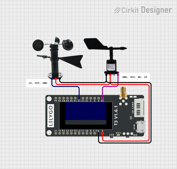
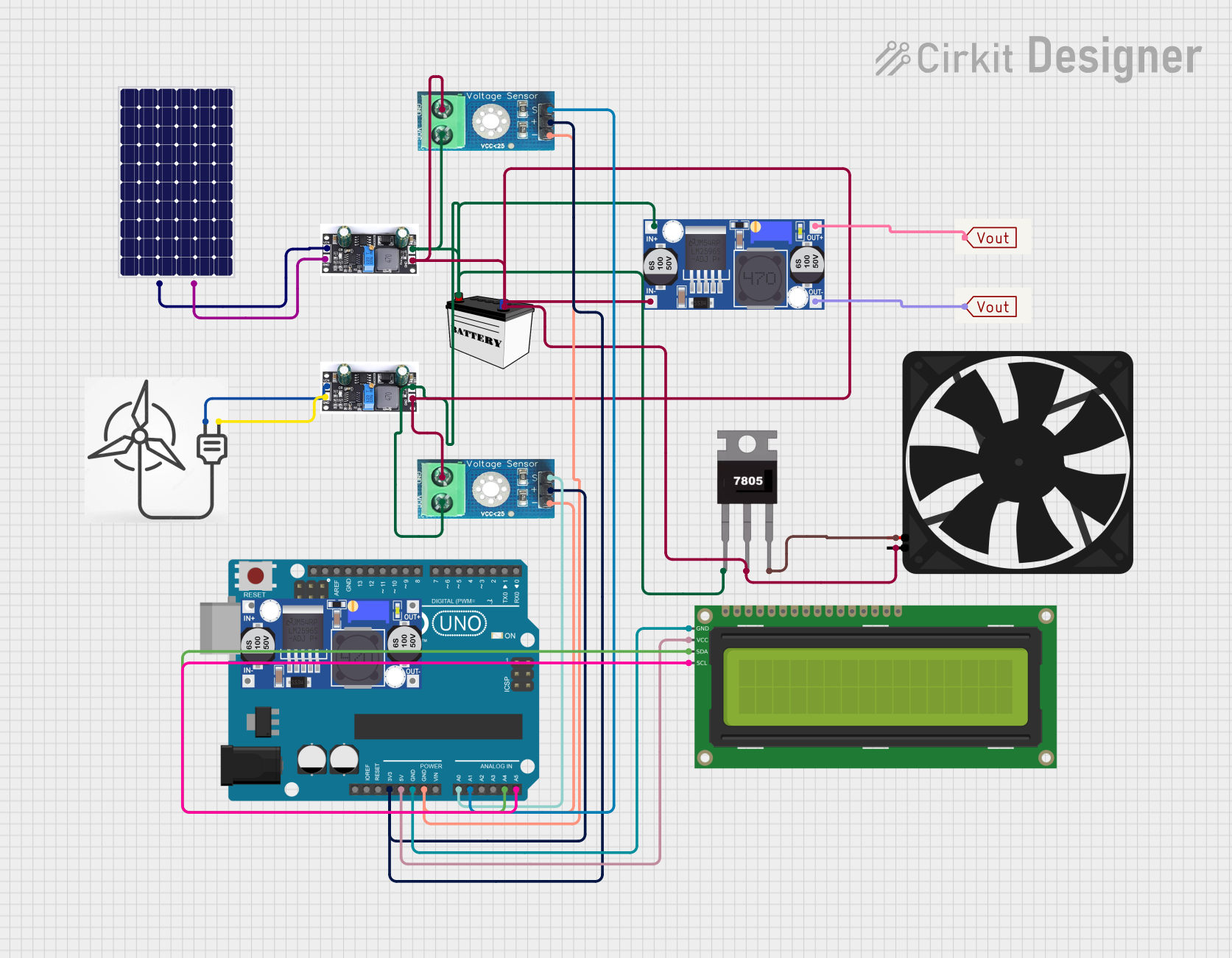
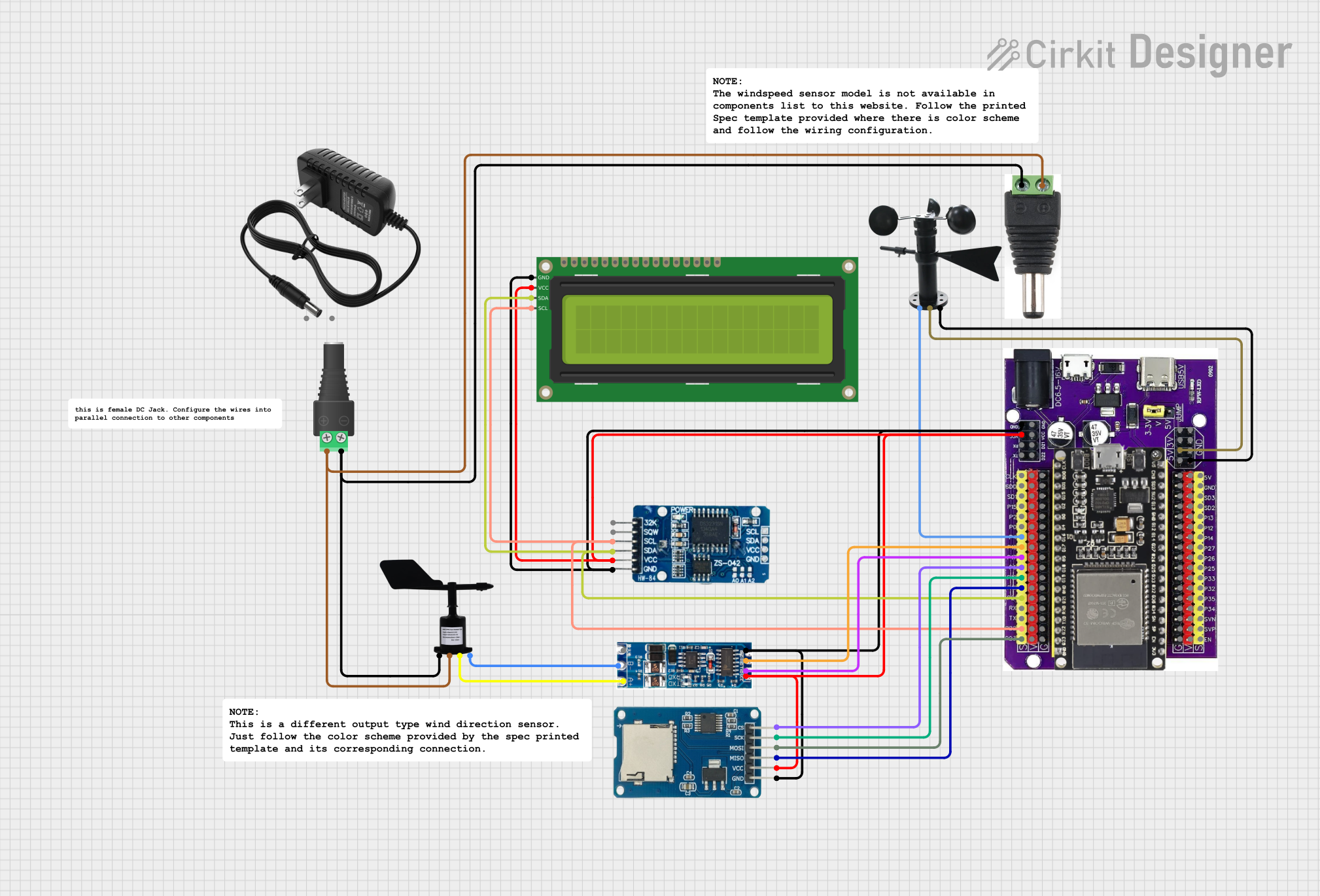
Explore Projects Built with wind
Common Applications and Use Cases
- Residential wind power generation
- Educational kits for renewable energy
- Remote power stations for sensors and communication devices
- DIY projects and prototypes involving renewable energy sources
Technical Specifications
Key Technical Details
| Specification | Value | Description |
|---|---|---|
| Rated Voltage | 12V DC | Optimal operating voltage |
| Maximum Current | 5A | Maximum current output |
| Rated Power | 60W | Maximum power output at rated voltage |
| Cut-in Wind Speed | 3 m/s | Minimum wind speed to start generation |
| Survival Wind Speed | 50 m/s | Maximum wind speed tolerable |
| Rotor Diameter | 1.2 meters | Diameter of the turbine blades |
| Weight | 3.5 kg | Total weight of the turbine |
Pin Configuration and Descriptions
| Pin Number | Name | Description |
|---|---|---|
| 1 | +Vout | Positive voltage output from the generator |
| 2 | GND | Ground connection |
| 3 | RPM Signal | Pulse signal proportional to rotation speed |
Usage Instructions
How to Use the Component in a Circuit
- Mounting the Turbine: Securely mount the Rover 5 wind turbine in a location with adequate wind exposure, ensuring it is well above any obstructions.
- Electrical Connections: Connect the +Vout pin to the positive rail of your circuit and the GND pin to the common ground.
- Load Connection: Attach the electrical load (battery, capacitor, or power regulator) to the output terminals, respecting the polarity.
- Monitoring RPM: The RPM Signal pin can be connected to a microcontroller, such as an Arduino UNO, to monitor the rotation speed of the turbine.
Important Considerations and Best Practices
- Always install the wind turbine in an open area free from obstructions that could affect wind flow.
- Ensure that the turbine is properly anchored and secured to prevent damage in high winds.
- Use appropriate gauge wires to handle the maximum current output.
- Incorporate a charge controller to protect batteries from overcharging.
- Regular maintenance checks are recommended to ensure optimal performance and longevity.
Troubleshooting and FAQs
Common Issues
- Low Power Output: Check for obstructions or incorrect installation that may be blocking wind flow. Ensure that the turbine is facing the direction of prevailing winds.
- No Power Output: Verify all electrical connections, and inspect the turbine for any physical damage to the blades or generator.
- Excessive Vibration: Make sure the turbine is securely mounted and that all bolts and connections are tight.
Solutions and Tips for Troubleshooting
- If the power output is lower than expected, consider repositioning the turbine or checking for mechanical issues with the blades or generator.
- In case of no power output, use a multimeter to check for continuity in the electrical connections and the integrity of the generator.
- For vibrations, balance the blades and ensure that the mounting pole is not resonating with the blade rotation frequency.
FAQs
Q: Can the Rover 5 be used in an urban environment? A: Yes, but it's important to ensure that local regulations allow for the installation of wind turbines and that there is sufficient wind flow.
Q: What maintenance is required for the Rover 5? A: Regular checks for loose fittings, wear and tear on the blades, and ensuring electrical connections are secure will help maintain the turbine's performance.
Q: How do I measure the RPM of the turbine? A: The RPM Signal pin provides a pulse signal that can be measured with a microcontroller. Here's an example code snippet for an Arduino UNO:
const int rpmPin = 2; // RPM Signal connected to digital pin 2
volatile int rpmCount = 0;

void setup() {
  Serial.begin(9600);
  attachInterrupt(digitalPinToInterrupt(rpmPin), countRPM, RISING);
}

void loop() {
  // Wait for 1 second
  delay(1000);
  // Disable interrupts to read rpmCount safely
  noInterrupts();
  int rpm = rpmCount * 60; // Calculate RPM
  rpmCount = 0; // Reset counter
  interrupts(); // Enable interrupts again
  Serial.print("RPM: ");
  Serial.println(rpm);
}

void countRPM() {
  rpmCount++; // Increment on each pulse from the turbine
}
Remember to keep code comments concise and within the 80-character line length limit.