How to Use Adafruit PiRTC PCF8523: Examples, Pinouts, and Specs
Introduction
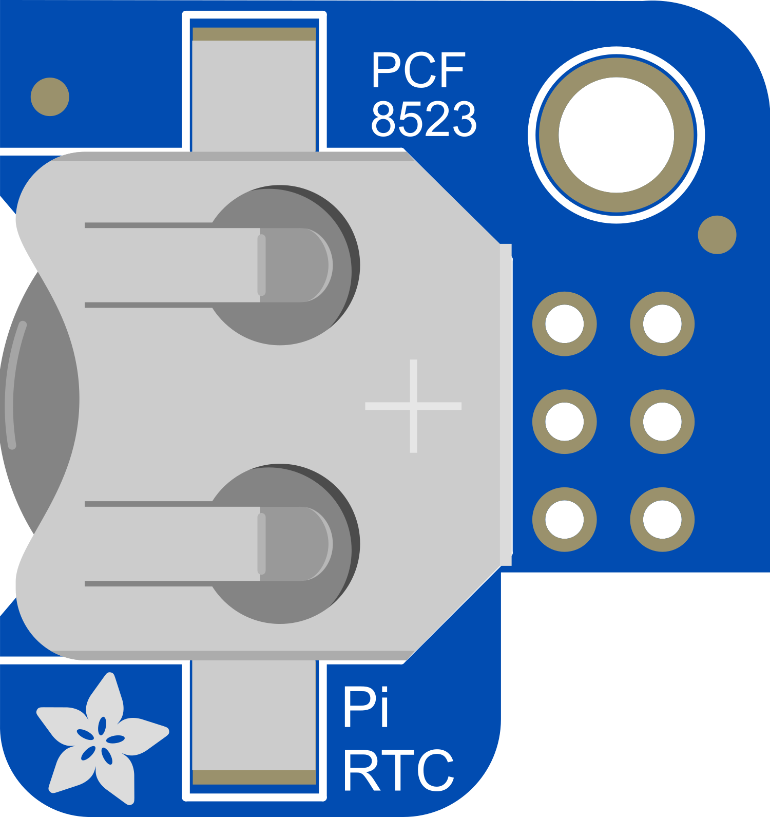
The Adafruit PiRTC PCF8523 is a real-time clock (RTC) module that provides accurate timekeeping capabilities to Raspberry Pi projects. It is an essential component for time-sensitive applications where the Raspberry Pi may not have a network connection to update the time. The module uses the NXP PCF8523 RTC chip and maintains the time with a coin cell battery, ensuring that the clock continues to run even when the Raspberry Pi is powered off.
Explore Projects Built with Adafruit PiRTC PCF8523

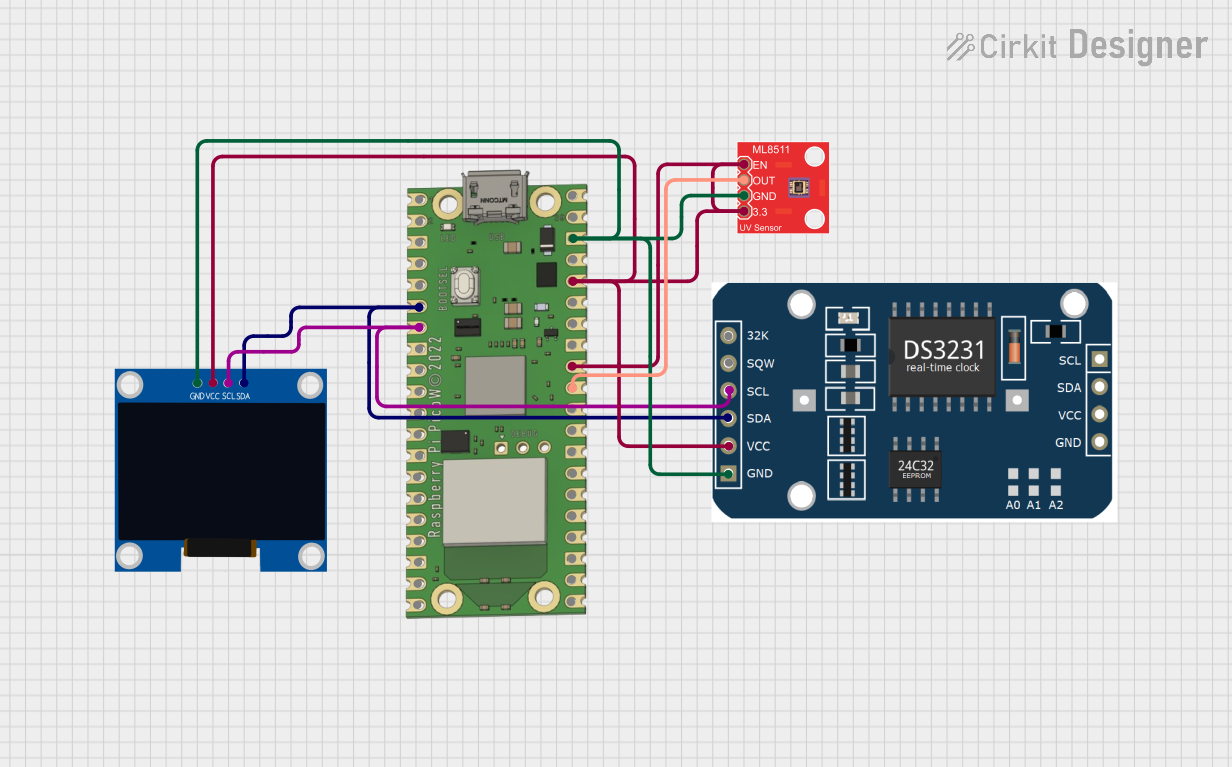
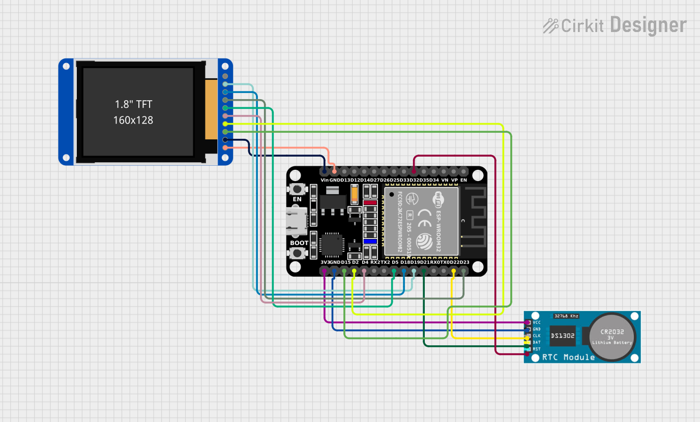

Explore Projects Built with Adafruit PiRTC PCF8523
Common Applications and Use Cases
- Data logging with time stamps
- Alarm clocks and schedule-based automation
- Time-based authentication systems
- Maintaining file system integrity with accurate timestamps
Technical Specifications
Key Technical Details
- Voltage: 3.3V (compatible with Raspberry Pi logic levels)
- Current: 55 μA at 3.3V (typical timekeeping current)
- Battery Backup: CR1220 coin cell battery (not included)
- I2C Interface: Address 0x68 (default)
Pin Configuration and Descriptions
| Pin Number | Name | Description |
|---|---|---|
| 1 | GND | Ground connection |
| 2 | VCC | Power supply (3.3V) |
| 3 | SDA | I2C Data Line |
| 4 | SCL | I2C Clock Line |
| 5 | SQW | Square Wave/Interrupt Output (not used by default) |
Usage Instructions
Connecting to a Raspberry Pi
- Power Off the Raspberry Pi: Before connecting the module, ensure the Raspberry Pi is powered off to avoid any electrical damage.
- Connect to I2C Pins: Connect the SDA and SCL pins of the PiRTC to the corresponding SDA (GPIO 2) and SCL (GPIO 3) pins on the Raspberry Pi's GPIO header.
- Connect Power: Connect the VCC pin to a 3.3V pin on the Raspberry Pi and the GND pin to a ground pin.
- Insert Battery: Place a CR1220 coin cell battery into the battery holder on the PiRTC module.
Software Setup
- Enable I2C Interface: Use
raspi-configor the Raspberry Pi Configuration tool to enable the I2C interface. - Install RTC Libraries: Install the necessary libraries and tools to interact with the RTC module.
- Set the Time: Write the current time to the RTC module using the appropriate commands or software tools.
- Read the Time: Configure the Raspberry Pi to read the time from the RTC module on boot.
Important Considerations and Best Practices
- Always handle the module with care to avoid electrostatic discharge (ESD) damage.
- Ensure the battery is inserted correctly with the positive side facing up.
- Verify that the I2C address does not conflict with other devices on the I2C bus.
- Use pull-up resistors on the SDA and SCL lines if multiple devices are connected to the I2C bus.
Troubleshooting and FAQs
Common Issues
- Time Not Maintaining: Ensure the battery is inserted correctly and has sufficient charge.
- I2C Communication Errors: Check the wiring and connections, and ensure that the I2C interface is enabled on the Raspberry Pi.
- Module Not Recognized: Verify that the correct I2C address is being used and that there are no conflicts with other devices.
Solutions and Tips
- Use the
i2cdetectcommand to verify that the Raspberry Pi can detect the RTC module on the I2C bus. - If the time drifts significantly, consider replacing the battery or checking for sources of electromagnetic interference.
FAQs
Q: Can the PiRTC module be used with other microcontrollers? A: Yes, as long as the microcontroller supports I2C communication and operates at 3.3V logic levels.
Q: How long will the battery last? A: The battery life depends on the quality of the battery and the environmental conditions but typically lasts for several years.
Q: Does the module automatically handle daylight saving time changes? A: No, daylight saving time changes must be handled by the operating system or user application.
Example Code for Raspberry Pi
Below is an example Python script to set and read the time from the Adafruit PiRTC PCF8523 module using the smbus library. This script assumes that the I2C interface has been enabled and the smbus library is installed on the Raspberry Pi.
import smbus
import time
I2C bus (usually bus 1 on newer Raspberry Pis)
bus = smbus.SMBus(1)
PCF8523 address on the I2C bus
RTC_ADDRESS = 0x68
Register addresses within the RTC
RTC_SECONDS_REG = 0x03 RTC_MINUTES_REG = 0x04 RTC_HOURS_REG = 0x05
... (additional register addresses for other time components)
def set_time(hours, minutes, seconds): """Set the time on the RTC.""" # Write to RTC registers to set the time bus.write_byte_data(RTC_ADDRESS, RTC_SECONDS_REG, seconds) bus.write_byte_data(RTC_ADDRESS, RTC_MINUTES_REG, minutes) bus.write_byte_data(RTC_ADDRESS, RTC_HOURS_REG, hours)
def read_time(): """Read the current time from the RTC.""" # Read from RTC registers to get the current time seconds = bus.read_byte_data(RTC_ADDRESS, RTC_SECONDS_REG) minutes = bus.read_byte_data(RTC_ADDRESS, RTC_MINUTES_REG) hours = bus.read_byte_data(RTC_ADDRESS, RTC_HOURS_REG) return hours, minutes, seconds
Example usage
set_time(12, 34, 56) # Set time to 12:34:56 time.sleep(1) # Wait for a second current_time = read_time() print(f"Current Time: {current_time[0]:02}:{current_time[1]:02}:{current_time[2]:02}")
Please note that this example does not handle the conversion of binary-coded decimal (BCD) values, which is how the PCF8523 stores time. Additional code is required to convert between BCD and integer values for proper time setting and reading.