Cirkit Designer Logo
Cirkit Designer
Your all-in-one circuit design IDE
Home / 
Component Documentation

How to Use Magentic lock: Examples, Pinouts, and Specs

Image of Magentic lock
Cirkit Designer LogoDesign with Magentic lock in Cirkit Designer

Introduction

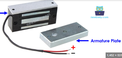
The Halim 05 Magnetic Lock (commonly referred to as a maglock) is an electronic locking device that utilizes an electromagnet to secure doors. This component is widely used in access control systems, providing a robust and reliable locking mechanism that can be controlled remotely. Its applications range from residential and commercial buildings to industrial facilities, ensuring security and controlled access.

Explore Projects Built with Magentic lock

Use Cirkit Designer to design, explore, and prototype these projects online. Some projects support real-time simulation. Click "Open Project" to start designing instantly!
Arduino UNO RFID Door Lock System with Buzzer and LED Indicators
Image of Door Lock System2: A project utilizing Magentic lock in a practical application
This circuit is an RFID-based door lock system controlled by an Arduino UNO. It uses an NFC/RFID reader to read tags and controls a magnetic lock via a relay, with visual feedback provided by red and green LEDs and audio feedback from a buzzer. Authorized RFID tags unlock the door, while unauthorized tags trigger a different buzzer sound and LED indication.
Cirkit Designer LogoOpen Project in Cirkit Designer
RFID-Enabled Arduino Door Lock System with LCD Feedback
Image of RFID door lock sensor: A project utilizing Magentic lock in a practical application
This circuit is designed as an RFID-based door lock system. It uses an Arduino Micro to control a solenoid lock, read RFID tags with an RFID-RC522 module, provide visual feedback through red and green LEDs, and audible feedback with a piezo buzzer. The system also includes an LCD screen to display messages to the user, and a pushbutton to manually trigger the lock mechanism.
Cirkit Designer LogoOpen Project in Cirkit Designer
Arduino UNO RFID Door Lock System with Relay and Buzzer Notification
Image of Door Lock System: A project utilizing Magentic lock in a practical application
This circuit is designed as an RFID-based access control system that operates a magnetic door lock. The Arduino UNO reads RFID tags using the RFID-RC522 module and controls a magnetic lock via a 12V relay, indicating access status with red and green LEDs and a buzzer. The system grants or denies access based on the RFID tag presented, unlocking the door for authorized tags and sounding an alert for unauthorized attempts.
Cirkit Designer LogoOpen Project in Cirkit Designer
Arduino UNO Bluetooth-Controlled Smart Locker with Servo Motor
Image of door lock: A project utilizing Magentic lock in a practical application
This circuit is a smart locker system controlled by an Arduino UNO, which uses an HC-05 Bluetooth module for wireless communication, a servo motor for locking and unlocking, and an IR sensor for proximity detection. The system is powered by a 12V battery with a buck converter to step down the voltage, and it includes an LCD display for user interface.
Cirkit Designer LogoOpen Project in Cirkit Designer

Explore Projects Built with Magentic lock

Use Cirkit Designer to design, explore, and prototype these projects online. Some projects support real-time simulation. Click "Open Project" to start designing instantly!
Image of Door Lock System2: A project utilizing Magentic lock in a practical application
Arduino UNO RFID Door Lock System with Buzzer and LED Indicators
This circuit is an RFID-based door lock system controlled by an Arduino UNO. It uses an NFC/RFID reader to read tags and controls a magnetic lock via a relay, with visual feedback provided by red and green LEDs and audio feedback from a buzzer. Authorized RFID tags unlock the door, while unauthorized tags trigger a different buzzer sound and LED indication.
Cirkit Designer LogoOpen Project in Cirkit Designer
Image of RFID door lock sensor: A project utilizing Magentic lock in a practical application
RFID-Enabled Arduino Door Lock System with LCD Feedback
This circuit is designed as an RFID-based door lock system. It uses an Arduino Micro to control a solenoid lock, read RFID tags with an RFID-RC522 module, provide visual feedback through red and green LEDs, and audible feedback with a piezo buzzer. The system also includes an LCD screen to display messages to the user, and a pushbutton to manually trigger the lock mechanism.
Cirkit Designer LogoOpen Project in Cirkit Designer
Image of Door Lock System: A project utilizing Magentic lock in a practical application
Arduino UNO RFID Door Lock System with Relay and Buzzer Notification
This circuit is designed as an RFID-based access control system that operates a magnetic door lock. The Arduino UNO reads RFID tags using the RFID-RC522 module and controls a magnetic lock via a 12V relay, indicating access status with red and green LEDs and a buzzer. The system grants or denies access based on the RFID tag presented, unlocking the door for authorized tags and sounding an alert for unauthorized attempts.
Cirkit Designer LogoOpen Project in Cirkit Designer
Image of door lock: A project utilizing Magentic lock in a practical application
Arduino UNO Bluetooth-Controlled Smart Locker with Servo Motor
This circuit is a smart locker system controlled by an Arduino UNO, which uses an HC-05 Bluetooth module for wireless communication, a servo motor for locking and unlocking, and an IR sensor for proximity detection. The system is powered by a 12V battery with a buck converter to step down the voltage, and it includes an LCD display for user interface.
Cirkit Designer LogoOpen Project in Cirkit Designer

Technical Specifications

Key Technical Details

Parameter Value
Operating Voltage 12V DC
Current Draw 500mA
Holding Force 600 lbs (272 kg)
Dimensions 250mm x 48mm x 25mm
Weight 2.5 kg
Operating Temperature -10°C to 55°C
Humidity 0% to 95% (non-condensing)

Pin Configuration and Descriptions

Pin Number Pin Name Description
1 VCC Power supply input (12V DC)
2 GND Ground
3 NC Normally Closed contact
4 COM Common contact
5 NO Normally Open contact

Usage Instructions

How to Use the Component in a Circuit

To integrate the Halim 05 Magnetic Lock into a circuit, follow these steps:

  1. Power Supply Connection: Connect the VCC pin to a 12V DC power supply and the GND pin to the ground.
  2. Control Signal: Use a relay or a transistor to control the power to the magnetic lock. This allows you to control the lock remotely using a microcontroller like an Arduino.
  3. Access Control Integration: Connect the NC, COM, and NO pins to your access control system. These pins can be used to monitor the lock status and trigger alarms if necessary.

Important Considerations and Best Practices

  • Power Supply: Ensure that the power supply can provide sufficient current (at least 500mA) to the magnetic lock.
  • Heat Dissipation: The lock may generate heat during operation. Ensure proper ventilation to avoid overheating.
  • Mounting: Securely mount the magnetic lock and the armature plate to ensure proper alignment and maximum holding force.
  • Safety: Implement fail-safe mechanisms in your access control system to unlock the door in case of power failure.

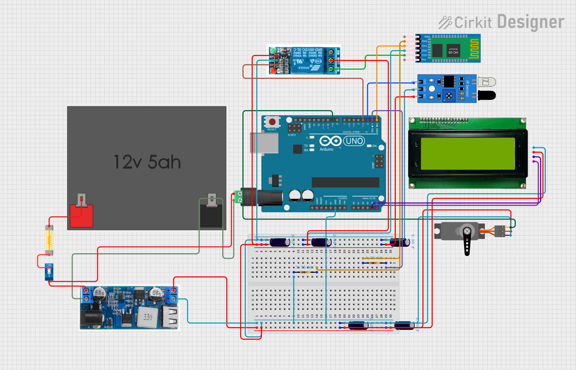
Example Circuit with Arduino UNO

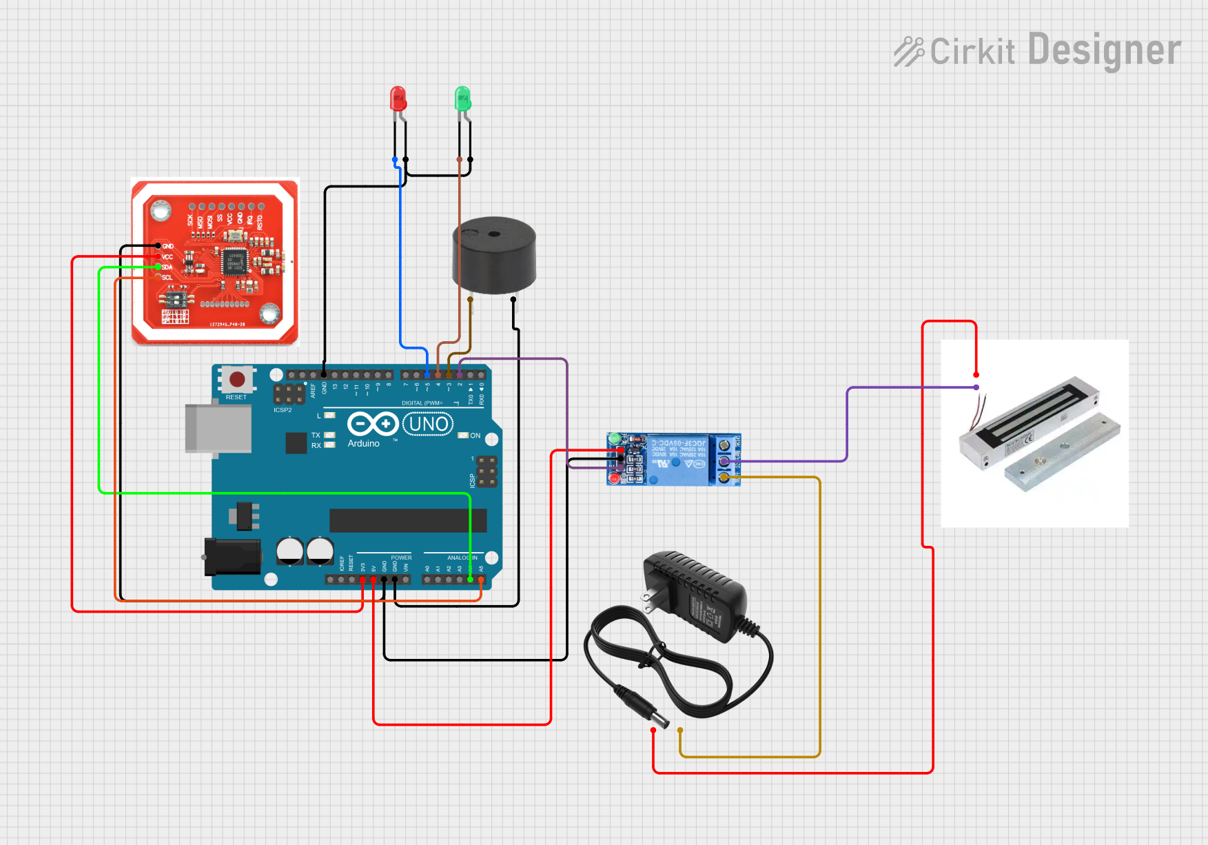
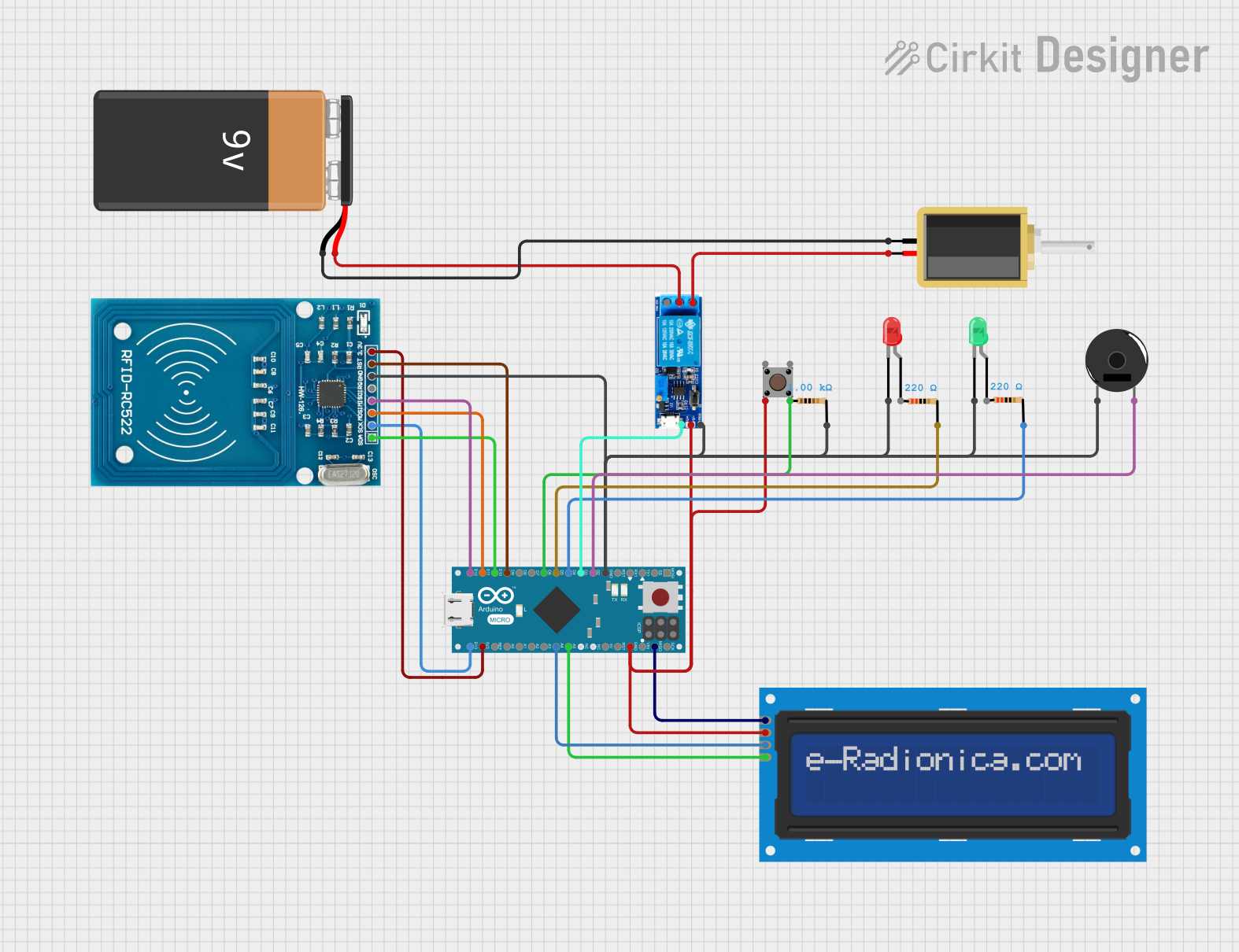
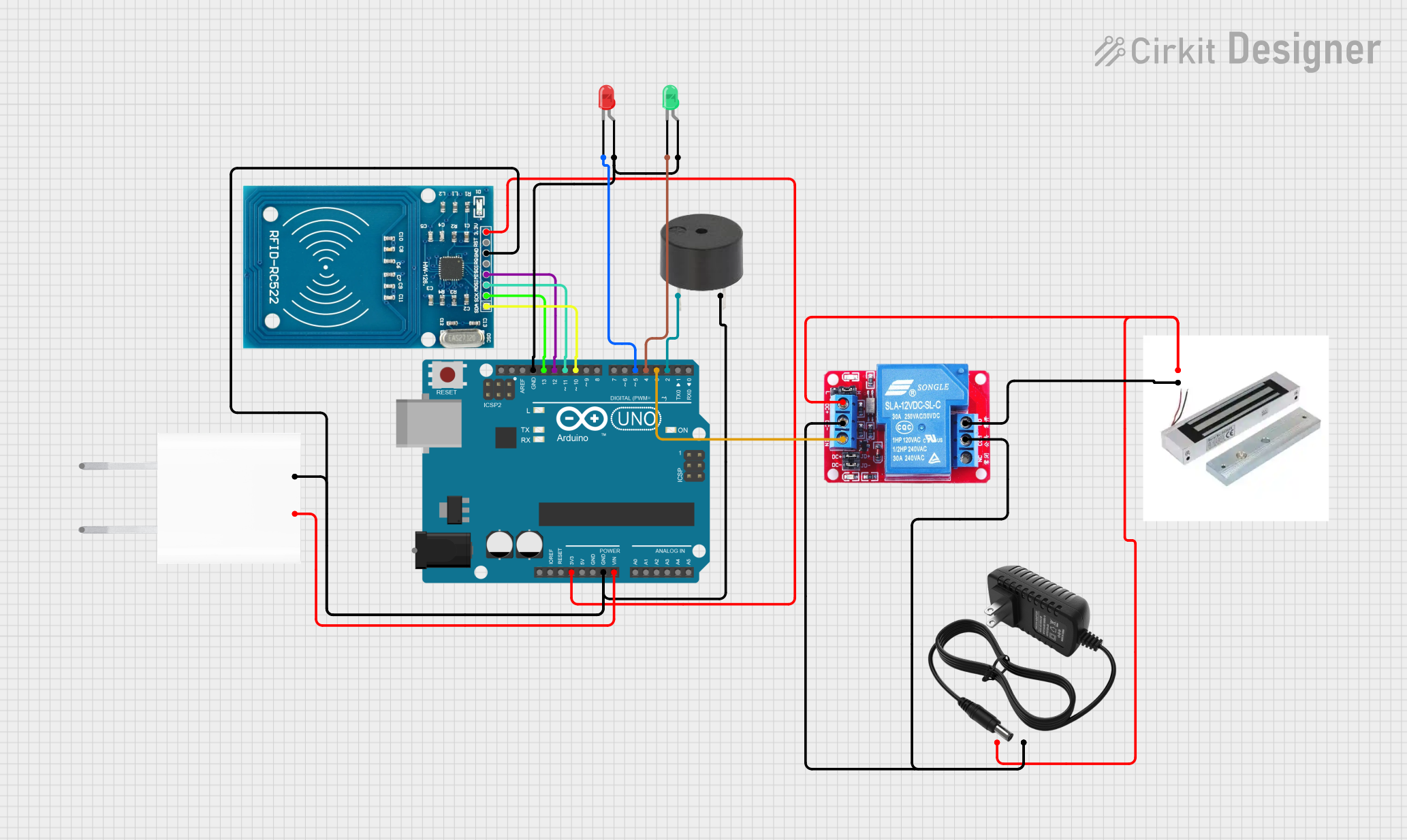
Below is an example of how to control the Halim 05 Magnetic Lock using an Arduino UNO and a relay module.

Circuit Diagram

Arduino UNO       Relay Module       Magnetic Lock
-----------       ------------       -------------
  5V  ----------- VCC
 GND  ----------- GND
 D7   ----------- IN
 GND  ----------- GND
                  COM  ------------- VCC (12V DC)
                  NO   ------------- VCC (Magnetic Lock)
                  NC   ------------- GND (Magnetic Lock)

Arduino Code

// Magnetic Lock Control using Arduino UNO
const int relayPin = 7; // Pin connected to relay module

void setup() {
  pinMode(relayPin, OUTPUT); // Set relay pin as output
  digitalWrite(relayPin, LOW); // Initially turn off the relay
}

void loop() {
  // Example: Lock the door
  digitalWrite(relayPin, HIGH); // Turn on the relay to lock the door
  delay(5000); // Keep the door locked for 5 seconds

  // Example: Unlock the door
  digitalWrite(relayPin, LOW); // Turn off the relay to unlock the door
  delay(5000); // Keep the door unlocked for 5 seconds
}

Troubleshooting and FAQs

Common Issues Users Might Face

  1. Magnetic Lock Not Engaging:

    • Solution: Check the power supply and ensure it provides 12V DC and sufficient current (500mA). Verify the connections to the VCC and GND pins.
  2. Lock Generates Excessive Heat:

    • Solution: Ensure proper ventilation around the lock. Check for any obstructions that may impede heat dissipation.
  3. Lock Not Holding Properly:

    • Solution: Verify the alignment between the magnetic lock and the armature plate. Ensure both surfaces are clean and free from debris.
  4. Relay Not Controlling the Lock:

    • Solution: Check the connections between the Arduino, relay module, and magnetic lock. Ensure the relay module is receiving the correct control signal from the Arduino.

FAQs

Q1: Can I use a different voltage power supply?

  • A1: No, the Halim 05 Magnetic Lock is designed to operate at 12V DC. Using a different voltage may damage the lock or reduce its performance.

Q2: How do I know if the lock is engaged?

  • A2: You can use the NC, COM, and NO pins to monitor the lock status. When the lock is engaged, the NC and COM pins will be connected.

Q3: Can I control the lock with a different microcontroller?

  • A3: Yes, you can control the lock with any microcontroller that can provide a control signal to a relay or transistor.

Q4: What happens if there is a power failure?

  • A4: The magnetic lock will disengage in the event of a power failure. Implement fail-safe mechanisms in your access control system to handle such scenarios.

This documentation provides a comprehensive guide to using the Halim 05 Magnetic Lock. By following the instructions and best practices outlined, you can ensure reliable and secure operation in your access control systems.